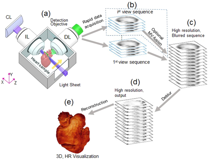
Figure 1. Implementation of cardiac Light-Sheet Fluorescence Microscopy (LSFM).
(a) The optical setting of LSFM. A laser beam (purple) is collected and focused by the beam expander to optimize the beam size. A cylindrical lens (CL) converts the laser beam to a sheet of laser light to illuminate a thin layer of the sample. The sample is mounted at the intersection of the illumination lens (IL) and detection lens (DL). The illuminated 2-D layer (fluorescent detection in green) is captured by the high-frame rate CMOS camera. The illumination axis is orthogonal to the detection axis, and the illumination optics is designed to illuminate a very thin volume around the focal plane of the detection objective. The configurations of light-sheet illumination and fluorescence detection are highly tunable to accommodate for various heart samples. (b) The plane fluorescent images at different axial (z) depths are sequentially captured by the camera (c,d). For non-transparent fetal mouse hearts, multi-view (MV) techniques are applied to rotate the samples for multi-view imaging, followed by registering and fusing these views into a 3-D cardiac architecture. An iterative deconvolution technique is applied to the blurred sequence for high resolution. (e) A digitally reconstructed heart is accomplished by stacking the deconvolved images.

