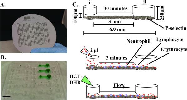
Figure 1. Photograph of microfluidic device and steps of operation.
A, Photograph of a silicone wafer mold of the device. B, Photograph of an arrayed polydimethylsiloxane (PDMS) device with 16 microfluidic channels. Black bar indicates 5 mm. C-E, Device operation. C, Add coating of P-selectin within the microfluidic device for 30 minutes. Dimensions of device channel are noted. Port i denotes the input port where fluids are added, port ii denotes the output port. D, Dilute blood within a reservoir and pipette ~2μl of blood within the channel, and allow neutrophils to adhere for 3 minutes. E, Add fluorescent dye mixture containing Hoechst (HCT) and dihydrorhodamine-123 (DHR). Fluid will flow from port I to port ii due to the difference in surface tension.

