
Figure 1.
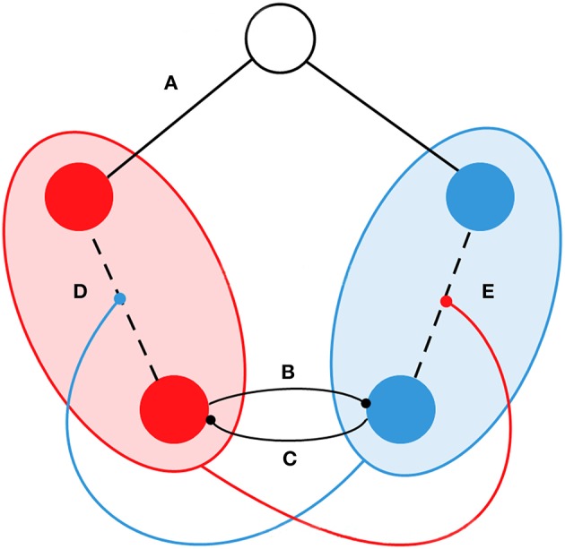
Schematic representation of the functional interactions in the model. Circles represent examples of five oscillators/nodes. SN and DMN are represented by red and blue respectively. The node in white indicates that it does not belong to the SN or DMN. We introduced the following types of dynamical interactions: (A) If the node does not belong to the SN or the DMN, the connectivity was fixed during simulations and it corresponded to the structural connectivity Cij. (B) The phase of nodes from the DMN competed with nodes from the SN. (C) The phase of nodes from the SN competed with nodes from the DMN. (D) Connectivity between nodes in the SN is proportionally weakened by the coherence of the DMN. (E) Connectivity between nodes in the DMN is proportionally weakened by the coherence of the SN.