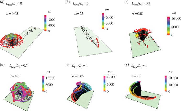
Figure 4.
Trajectories of S. oneidensis model with partially constrained flagellum. (a) Lfree/LT = 0 (flagellum completely adhered) and α = 0.05; (b) Lfree/LT = 0 and α = 25; (c) Lfree/LT = 0.3 and α = 0.05; (d) Lfree/LT = 0.7 and α = 0.05; (e) Lfree/LT = 1 (flagellum completely free) and α = 0.05; (f) Lfree/LT = 1 and α = 2.5. α is the ratio of the head spring constant and the flagellar motor torque. The black lines represent the axis of the head and the flagellum at snapshots in time. The end of the flagellum at each snapshot is shown by a small coloured spot and the end of the head is shown by a larger coloured spot. The colours correspond to the time of the snapshot, indicated by a colour scale bar for each trajectory.

