
Figure 2.
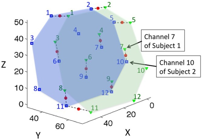
The location of coherence for a representative dyad. Green triangles represent the channel locations of subject 1; the green numbers label the channel indices; and the green area represents the probe coverage of subject 1. Blue squares and numbers represent the channel locations and indices of subject 2, and the blue area represents the probe coverage of subject 2. Channels were paired to their closest neighboring points within 15 mm distance, and the middle points of the paired channels were defined as the location of the coherence, represented by red dots. Dashed lines connect the paired channels for representative purposes.