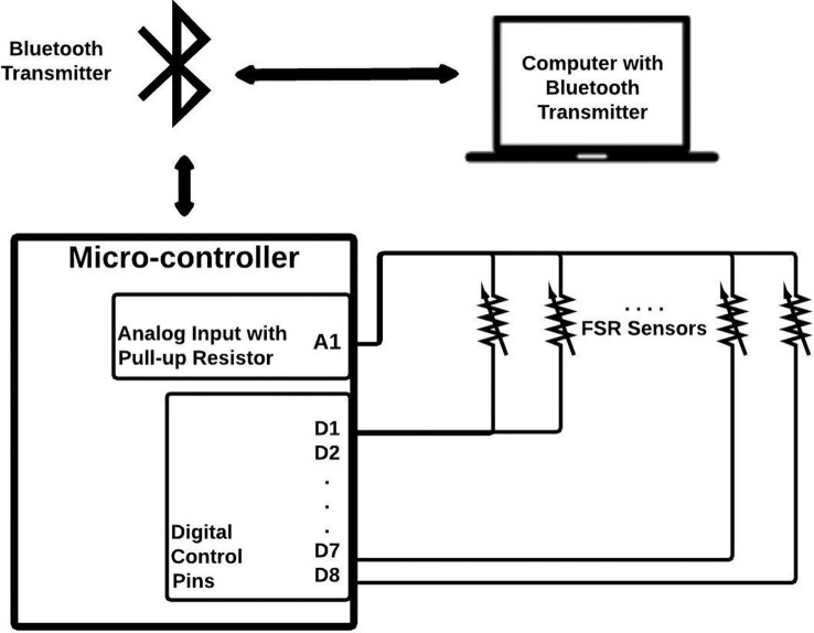
Figure 2.
Schematic for FMG signal extraction and transmission. There are two terminals for each FSR. One terminal is connected to a common analog input pin of an Arduino ProMini micro-controller with an internal pull-up resistor of 37.5 kΩ, and the other to a digital control pin. The eight FSR signals are digitized sequentially using the micro-controller and transmitted via a Bluetooth module to a personal computer for data collection.

