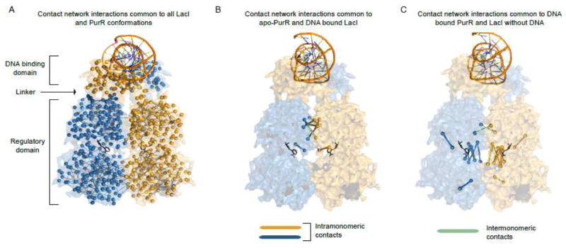
Figure 2.
Examples of residue contact-networks. Structures are represented as in Fig 1. For each panel, the network models are super-imposed over the space-filling model of the structure. For these contact networks, nodes are represented as the Cα atoms and the atomic contacts between two residues are represented as edges. Residues are considered to be in contact if any of their non-hydrogen atoms are within 5 Å of each other. (A) Network representation of the common noncovalent contacts that are present in all available PurR and LacI structures. (B) Network representation of the noncovalent contacts common to apo-PurR structures (no DNA bound) and LacI structures with DNA-bound. (C) Network representation of the noncovalent contacts common to LacI structures without DNA and DNA-bound-PurR conformations. Figures were prepared using Pymol [47].

