
Figure 1. Schematic rules of the failure-recovery strategy.
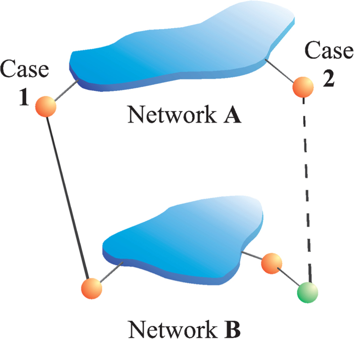
The GCs of networks A and B are shown (blue). In orange we mark boundary nodes at a distance  from their respectively GCs and in green a node with a distance
  from the GC in B. Case 1: Two interconnected failed nodes at a distance
  from their respectively GCs are repaired with probability γ. Case 2: If at least one of the two interconnected failed nodes is at a distance
  from its GC, we do not recover these nodes. Note that this type of recovery is practical and realistic, since in real infrastructure it is usually more convenient to repair boundary nodes which are next to the functional infrastructure GC.