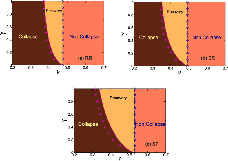
Figure 4.
Phase diagrams in the γ − p plane obtained from the theoretical approach and simulations for (a) RR networks with z = 5, (b) ER networks with  and (c) SF networks λ = 3 and
  . The symbols correspond to the simulations and the lines to the theory. The pink and magenta curves represent the values of γc as a function of p. The blue lines and symbols represent the values of pc for γ = 0.

