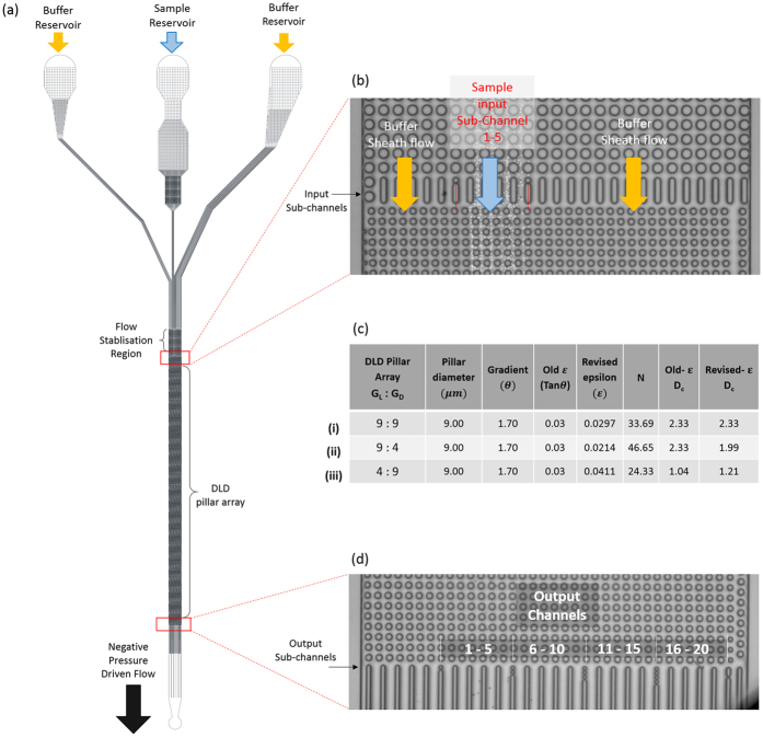
Figure 2. Device schematics and design with different DLD pillar array gap sizes.
The overall device schematics are shown in (a) where buffer and sample streams are loaded into reservoirs and driven into the device using extraction method by introducing a negative pressure using a syringe pump. As the three fluid input stream converges, a flow stabilization region is required to ensure consistent sample input flow within the sample input region of sub channel 1–5 shown in (b). Three DLD devices of different pillar array with gap size ranging from 9 μm:9 μm (i), 4 μm:9 μm (ii) and 9 μm:4 μm (iii). The output region of the device is sub-divided into 22 channels to enable a detailed characterization of the sample separation spectrum.

