Fig. 1.
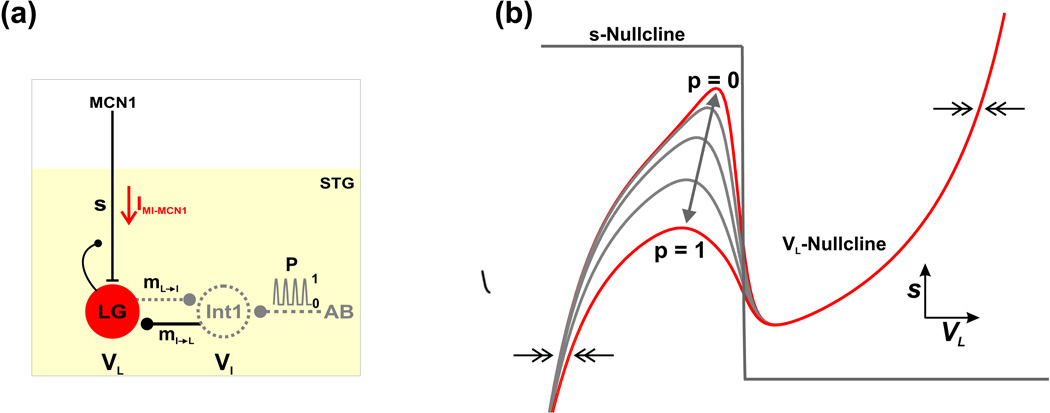
Circuit diagram and phase plane geometry of the reduced 2-dimensional model. (a) Circuit diagram. The neuron MCN1 projects to the STG to excite the gastric mill network. MCN1 and AB are modeled only through their synaptic influences. The LG neuron and Int1 reciprocally inhibit each other (mL→I and mI→L), and their membrane potentials are denoted by VL and VI, respectively. The LG neuron receives slow excitatory synaptic input from MCN1 (s; gated by the activation of a fast inward current IMI-MCN1) and presynaptically inhibits MCN1. Int1 is inhibited by a periodic, pyloric-timed synaptic input (p) from the pacemaker neuron (AB) of the pyloric circuit. Int1 is modeled implicitly (dashed; see Methods). (b) Phase plane geometry of the 2-dimensional model. The cubic- and step-function-shaped nullclines correspond to the steady-states of VL and s, respectively. The forcing parameter p (Equation (17)) results in a family of cubic VL-nullclines, where the highest/lowest cubic (p = 0/1) corresponds to zero/maximal pyloric input. As p varies between 0 and 1 (double-headed arrow) the VL-nullcline shifts between the two extremes. The pyloric-timed input is gated out when LG is active and, as a result, the right branch of the cubic is not affected by p. The 2-dimensional model resides in a relaxation (fast-slow) regime where the flow in the VL direction (double arrows) is much faster than the flow in the s direction.

