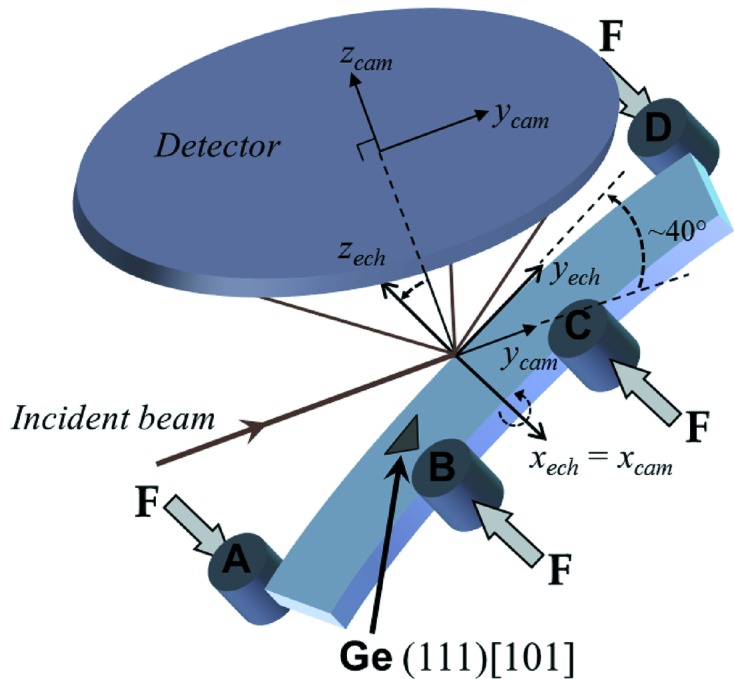
Figure 5.

Schematic sample arrangement for in situ four-point bending measurements. The Si sample is scanned along direction  , and at each position a Laue pattern is recorded on the CCD detector. A Ge single-crystal is used to calibrate the experimental geometry. The index ‘cam’ stands for the detector frame and the index ‘ech’ for the sample frame. Axis
  lies along the specimen length (longitudinal direction),
  along the specimen width (transverse direction), which is also the loading direction, and
  along the bending axis (normal direction).
