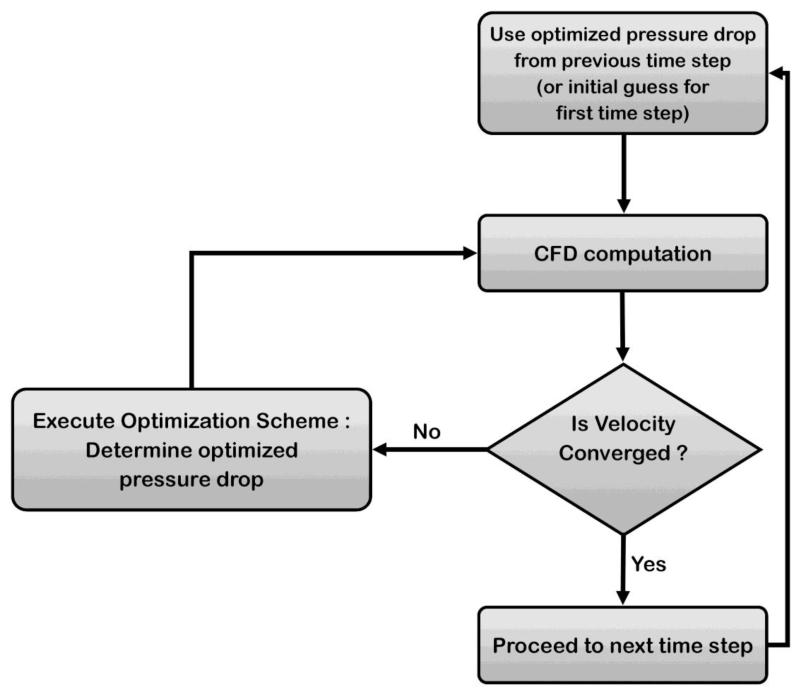
Figure 4.
Schematic of optimization procedure. For each time step, we begin with an initial ΔP: the optimized ΔP from the previous step, or an user-input initial guess for the very first time step. Using ΔP as the inlet boundary conditions, CFD computations are performed. Velocity data is then extracted from the simulation results and compared to the measured velocity data at the selected point q. If the velocity is converged (difference between computed and measured velocities at point q < 1%), the procedure moves to the next time step, otherwise ΔP is updated through the optimization scheme (Equation 3).

