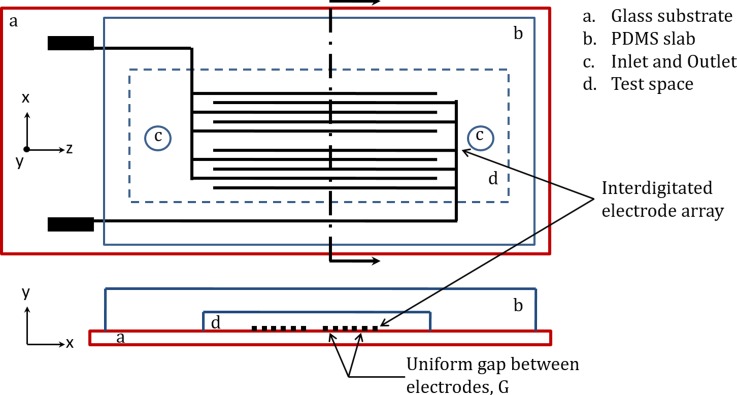
FIG. 3.
Schematic of the experimental chamber. Top frame (top view) shows the layout of bar interdigitated electrodes. The test compartment has insulating walls and ceiling, made of polydimethylsiloxane (PDMS). Two access holes for suspension loading/unloading are shown. Bottom frame (cross sectional view) shows test chamber formed by bottom glass substrate and top PDMS slab. Electrodes are located at the bottom of test chamber, patterned on the glass substrate (figure not drawn to scale).

