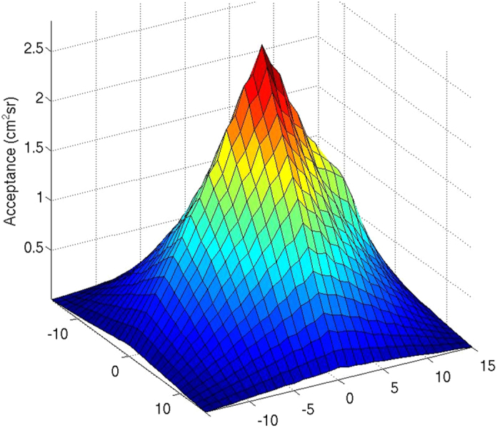
Figure 9. Telescope experimental acceptance for the configuration shown in Fig. (1).

The acceptance maximum value,  = 2.80 cm2 sr is obtained for the line of sight perpendicular to the detector planes and corresponding to (x, y) = (0, 0). The x and y coordinates represent the horizontal offsets between the pixels defining a given line of sight of the telescope (one pixel in the upper detection matrix, and the other one in the lower matrix). The acceptance integrated over the instrument entire detection surface equals
  = 630 cm2 sr for a solid angle aperture Ωint = 0.161 sr.
