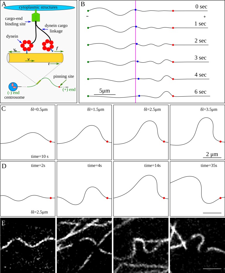
Fig 2. Simulations of dynein mediated bend formation in microtubules.
(A) The cartoon illustrates a model for the dynein-generated force on a microtubule. A net tangential force is experienced by the microtubule due to collective motor activity. (B) Simulated bend development by tangential forces using the model represented in A. The red dot is the location of the pinning site, the green dot indicates the minus end of the microtubule, and the blue dot is a point that marks the beginning of the microtubule segment that would be observed in a typical experiment. The magenta colored line marks initial position of the blue dot. The figure shows microtubule translation due to cytoskeletal dynein motors. The excess length behind the blue marker translates into the viewing window by motor activity, leading to a pronounced bend on the minus side of the pinning point. The excess length is equal to the maximum displacement of the blue marker from its original position. (C) Simulated shapes from varying excess lengths, generated after 10 seconds. (D) Snapshots of a segment of a microtubule at different times, showing how different shapes can develop if the microtubule is pinned for a long time (excess length of 2.5 μm). (E) Microtubule shapes observed in living cells.

