Fig 4.
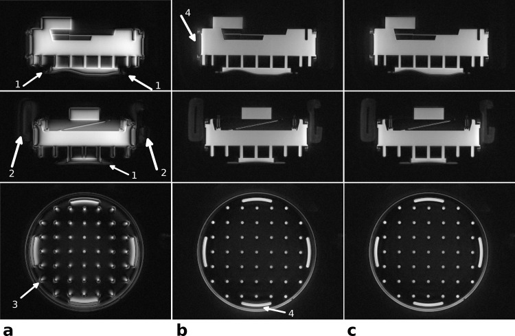
Phantom images—the effect of delay correction: Images in three orthogonal planes of a structure phantom reconstructed without gradient delay correction (a), with global delay correction as extracted from the template (b), and with both global delay and axis-specific delays (c). Without delay correction the visibility of the short T2 rubber gasket (arrows 1) and the restraining pads of the head coil (arrows 2) is strongly reduced (a). The strength of the delay effects depends on the distance from iso-center (see arrow 3), where the outermost structures show the strongest signal shift. The applied automatic global delay correction in (b) highly reduces these artifacts, but diffuse signal outside the object is still visible in some directions (arrows 4). These signal shifts can be further reduced by applying manual, axis specific delay corrections of, in this case, Δtx = +0.75 μs, Δty = −0.1 μs and Δtz = 0.0 μs.

