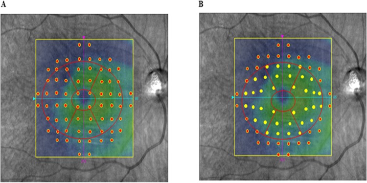
Fig 2. Image showing the ganglion cell analyzer and before and after the adjustment for the retinal ganglion cell displacement.
(A) The 10–2 VF displaced points. (B) The 10–2 VF displaced points corresponded to the RGC locations. These locations were based on a model that was derived from a previous histological analysis.13 After dividing the GCA thickness areas into the upper and lower hemifield sectors, either MAIATM, MP-3, or HFA was used to obtain the corresponding VF regions.

