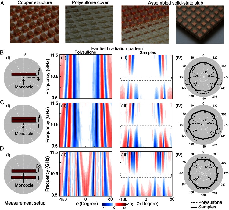
Fig. 3.
Experimental measurements of the fabricated samples. (A) Slab samples composed of closely arranged corrugated wires. (B) Experimental far-field radiation pattern measured for a single layer of slab. (B, I) Experimental setup; (B, II and III) measured field amplitude for an identical PSU slab and the sample slab; and (B, IV) radiation pattern. (C) Measurement for two stacked layers. (D) Measurement for two spaced slabs. d is 20 mm. The radiation patterns in polar coordinates are plotted with data at 10.4 GHz.

