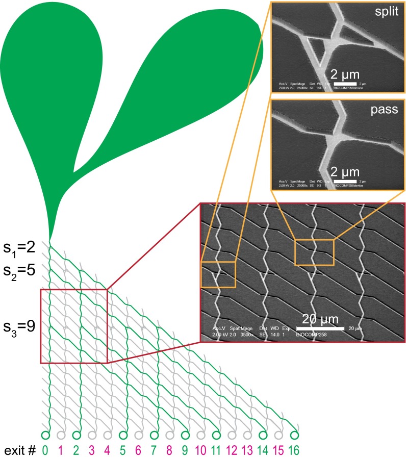
Fig. 2.
Device layout of a computation device for the SSP {2, 5, 9}. Schematic of the actual device layout used for microtubules, including the loading zones for the microtubules (green balloon-like areas), the channels traversed by the microtubules during calculation (green lines), and the channels that should not be traversed (gray lines). Exit numbers corresponding to correct results are shown in green; numbers corresponding to incorrect results are shown in magenta. The circles at each exit are designed to store filaments for easy readout. (Insets) Scanning electron micrographs of parts of the network used for microtubules, showing a split- and a pass junction. See SI Appendix, section S2 for a corresponding schematic layout of the device that was used with actin filaments, including details of the rectifiers used for that device.

