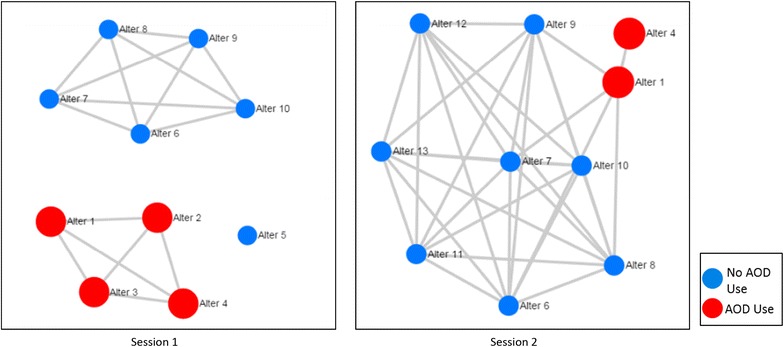
Fig. 2.

Hypothetical MNI participant network visualizations across two sessions. Each diagram demonstrates network members (“alters”) with circles (“nodes”) and lines (“edges”) connecting alters who have interacted with each other in the past 2 weeks. The left hand diagram (Session 1) depicts a network of ten nodes with two separate groups (“components”) and one network member who had no interactions with other alters (an “isolate”). One component in Session 1 is comprised of all AOD users and the other includes no AOD users. The right hand diagram shows that three of session 1 network members are no longer part of the network and three new members have been added to the network
