Abstract
Three dimensional imaging techniques are needed for the evaluation and assessment of biomaterials used for tissue engineering and drug delivery applications. Hydrogels are a particularly popular class of materials for medical applications but are difficult to image in tissue using most available imaging modalities. Imaging techniques based on X-ray Phase Contrast (XPC) have shown promise for tissue engineering applications due to their ability to provide image contrast based on multiple X-ray properties. In this manuscript, we investigate the use of XPC for imaging a model hydrogel and soft tissue structure. Porous fibrin loaded poly(ethylene glycol) hydrogels were synthesized and implanted in a rodent subcutaneous model. Samples were explanted and imaged with an analyzer-based XPC technique and processed and stained for histology for comparison. Both hydrogel and soft tissues structures could be identified in XPC images. Structure in skeletal muscle adjacent could be visualized and invading fibrovascular tissue could be quantified. There were no differences between invading tissue measurements from XPC and the gold-standard histology. These results provide evidence of the significant potential of techniques based on XPC for 3D imaging of hydrogel structure and local tissue response.
Key Terms: X-ray phase contrast, imaging, hydrogels, tissue engineering, micro-computed tomography
Introduction
There is a significant need for improved imaging methods for evaluating and monitoring biomaterials used in tissue engineering/regeneration, drug delivery, and cell therapies. Hydrogels are a particularly popular class of biomaterials, as they can be engineered with properties similar to soft tissues. Unfortunately, hydrogels present challenges when attempting to assess their properties in tissue. The material may be altered or lost due to disproportionate shrinkage during processing for histological analysis, and their high water content results in poor contrast in many non-invasive imaging modalities1. Furthermore, histological methods are destructive and often only allow two dimensional assessment of the samples. Therefore, there is a need for the development of other methods for the assessment of hydrogel structure in tissue in order for these biomaterials to be employed for clinical therapies. The ideal method would allow for three dimensional (3D), quantitative, non-invasive evaluation of both the hydrogel structure itself and the soft tissue at the interface with the biomaterials in order to monitor both the performance of the material and repair of the damaged tissue.
A number of biomedical imaging modalities have been investigated to visualize and assess biomaterials for tissue engineering applications both in vitro and in vivo1, 17, 33. These techniques have been utilized to study hydrogels with limited success. Autofluorescence exhibited by some natural6, 18, 42 and synthetic13 hydrogels allows for fluorescence imaging of structure and monitoring of degradation. However, this technique is primarily limited to in vitro applications. Hydrogels tagged with exogenous fluorescent makers5, 50 can be tracked both in vitro and in vivo, but poor tissue penetration means that these methods requires ectopic hydrogel implantation and the creation of a skin window chamber to mitigate scatter resulting from skin. Optical Coherence Tomography (OCT) has been implemented to image a variety of hydrogels for wound healing applications and has been successful for simultaneous monitoring of hydrogel degradation and skin formation27, 37, 41, 45. However, the resolution of OCT decreases with increasing penetration depth limiting its broad application. Ultrasound (US) imaging has been used to quantify hydrogel volumes over several weeks in vitro16, 21 and to detect and quantify spatial difference in collagen gel microstructures31. US elastography can be employed to measure viscoelastic properties of degrading hydrogels in vitro and in vivo25. While US methods have shown potential, they can be hindered by speckle noise and limited contrast of soft tissue formed in response to the hydrogel.
Magnetic Resonance Imaging (MRI) has also been employed to monitor hydrogels for tissue engineering and drug delivery applications. Implanted hydrogels were observed and their size quantified longitudinally with MRI36, 38. MRI also allowed for the visualization of the hydrogels and changes in local tissue response to the implanted hydrogels11, 12, 39. Further, MRI was used to reveal the integration of articular cartilage with a hydrogel by quantifying the width of transition and gradient between two materials in T2 weighted images35. MRI has also been used to non-invasively track the degradation of hydrogels with the incorporation of contrast agents24, 26, 46. New contrast mechanisms with MRI, such as chemical exchange saturation transfer MRI (CEST MRI), has enabled tracking degradation of hydrogels without the need for exogenous contrast agents29. CEST MRI is a contrast mechanism for the detection of certain molecules with rapidly exchangeable protons that can be saturated with specific radiofrequency pulses40. In Liang et. al the CEST MRI was limited to gelatin based hydrogels and may not correlate with structural changes to the gels but rather gelatin loss29. While imaging depth is high with MRI making it better than US and optical methods, spatial resolution is on the order of hundreds of microns. Better scanners are under development but, typically, spatial resolution is limited by signal to noise ratio, field of view, and acquisition time.
Hydrogels generate little or no contrast in absorption-based X-ray imaging techniques. However, imaging techniques based on X-ray phase contrast (XPC) have shown promise for imaging biomaterials and soft tissues with excellent depth penetration and high spatial resolution2, 9, 10, 22, 49. Contrast in XPC imaging results from X-ray absorption, refraction and ultra small angle scatter (USAXS), allowing materials and tissues with low X-ray absorption properties to be visualized and discriminated without the need for exogenous contrast agents.
The advantages of XPC imaging stem from the fact that, at diagnostic X-ray energies, the refractive-index variations of tissue are generally orders of magnitude greater than variations in the X-ray attenuation coefficient28. This is because refraction contrast decreases as the X-ray energy squared, whereas absorption contrast drops as the energy to the fourth power. Therefore, XPC imaging offers the potential for very-low-dose imaging4 by using X-ray energies that are traditionally considered too high to be useful for imaging soft tissue.
As opposed to conventional radiographic methods, XPC imaging requires the irradiating X-ray beam to possess a sufficient degree of coherence so that wave-like phenomenon such as refraction and interference can be observed. To understand the basic image formation principles of XPC imaging, consider an idealized scenario in which a monochromatic X-ray plane-wave Ui(x,y,z), propagating along the z-axis, irradiates an object. The transmitted wavefield Ut(x,y,z = 0) on the contact plane behind the object is given by34.
where
λ is the wavelength, and δ(r) and β(r)denote the real and imaginary components of the X-ray refractive index. The quantities ϕ(x,y) and μ(x,y) represent the projected phase and linear attenuation coefficient that characterize the object, respectively. Note that if the intensity on the contact plane were recorded, the resulting image would correspond to a conventional absorption-based radiography that is determined solely by the X-ray absorption properties.
An imaging system allows phase-contrast effects to be observed only when the transmitted X-ray wavefield Ut(x,y;0) is modified in some way prior to recording the intensity of the modified wavefield. In this way, variations in ϕ(x,y) introduced by the object can result in variations in the recorded intensity. The variations in the recorded image that are due to variations in ϕ(x,y) are referred to as phase contrast (PC) effects. In general, the raw measured image will have a mixed contrast that arises from both PC and conventional absorption contrast. In some implementations, multiple images are acquired that correspond to different configurations of the imaging system, and then computational methods can be utilized to un-mix the contrast mechanisms and obtain separate images that contain only PC or absorption contrast. Additionally, for some implementations, a third image can be computed that contains information regarding the ultra-small-angle-scattering properties of the object.
There are four implementations of X-ray PC imaging that are under development including Propagation-Based PC Imaging, X-ray Interferometry, Differential PC Imaging using X-ray Gratings, and Analyzer Based Imaging using Crystals. In analyzer methods (Figure 1B), an X-ray beam is prepared by use of a crystal monochromator, which results in a collimated and monochromated incident wavefield. This wavefield irradiates an object and is subsequently diffracted by an analyzer crystal. Based on properties of the analyzer crystal, X-rays travelling at or near the crystal’s Bragg angle are selected and ultimately passed on to the intensity detector. The analyzer crystal is rotated to different angles (on a microradian scale) and only the X-rays that satisfy Bragg’s condition will reflect and be detected. Measurements are taken at several different angles of the analyzer crystal in order to generate an angular intensity curve known as a rocking curve (Figure 1C). When an object is present in the pathway, changes in this rocking curve can be detected and used to reconstruct images that represent the absorption, refraction, and USAXS properties of the object.
Figure 1.
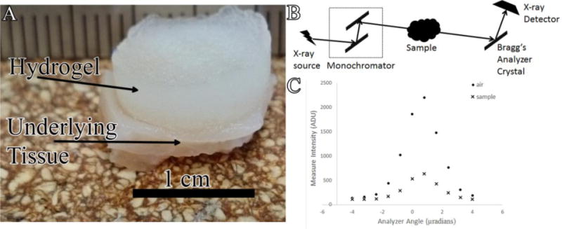
A) Photograph of explanted hydrogel-tissue sample B) Schematic of MIR imaging system at the NSLS X-ray beam produced by synchrotron is filtered to a single energy through monochromator and passed through the sample X-rays travelling at or near the Bragg’s angle of the analyzer crystal are reflected up to the X-ray detector C) Example of rocking curves acquired in the absence (●) and presence (x) of hydrogel sample.
The main objective of this study was to investigate an analyzer-based XPC imaging technique for 3D imaging of a model hydrogel system and soft tissue structure in a model tissue engineering system. We have previously shown that this technique allows visualization of hydrogels in culture and tissue sections9. XPC computed tomography (CT) is expected to enable imaging of both biomaterial and tissue structures in 3D and allow for quantification of tissue features. The tissues are imaged without the introduction of exogenous contrast agents resulting in contrast based on material and tissue properties alone.
Materials and Methods
Materials
Polyethylene glycol (PEG, Mn 8000), fibrinogen from human plasma (Fg, 50–70% protein), thrombin from human plasma (Tb), 2-hydroxy-2-methylpropiophenone (Irgacure 1173), acryloyl chloride (98%), and thriethylamine (TEA, 99.5%) were obtained from Sigma-Aldrich (St. Louis, MO). Sodium chloride (99.5%), dichloromethane (99.9%), and ethyl ether (anhydrous) were obtained from Fisher Scientific (Hampton, NH).
Preparation of fibrin loaded porous PEG hydrogels
The samples imaged were part of a larger study that was previously published23. A salt leaching technique that has been previously described13, 14 was adapted to make porous PEG scaffolds containing Tb. Briefly, PEG-diacrylate (PEG-DA) was synthesized by reaction of PEG (Mn 8000) with acryloyl chloride and TEA. The product was purified with dichloromethane dissolution and ethyl ether precipitation. The purified PEG-DA (250mg/ml) was then dissolved in saturated salt water, with Tb (100U/ml) and Irgacure 1173 (0.5% w/v, photoinitiator) added to form the hydrogel precursor. Two hundred microliters of the precursor was mixed with 200mg of sieved salt crystals (100–150μm in diameter) and polymerized under UV light (365nm) for 5 minutes. The salt crystals were then leached out in 50ml of DI water with agitation for 3 hours, replacing the DI water every hour.
Excessive water on the hydrogels surface was mostly removed by blotting with sterile gauze. The hydrogels were air-dried for 1 hour to allow evaporation of water in the pores. Three hundred microliter of Fg solution (10mg/ml, 20mg/ml or 40mg/ml) was dropped onto the porous hydrogel surface, and the solution absorbed into the pores by gravity and capillary force. The hydrogels were incubated at room temperature for 30 minutes to allow interaction of Fg with Tb to form a fibrin gel within the pores and then rinsed with DI water.
Animal model
All animal experiments were carried out at Edward Hines, Jr. VA Hospital, and the procedures were approved by the institutional animal care and use committee (IACUC). Fibrin loaded PEG hydrogels with 0, 10, 20 or 40mg/ml Fg were synthesized and prepared under sterile conditions. Polypropylene shells were fabricated in the shape of a top hat, with a height of 4 mm, a diameter of 10.5 mm, and an integral sewing ring of 3.55 mm extending from the open end of the hat.
Male Lewis rats (300g~400g) were anesthetized initially with 5% isofluorane via a nose cone and maintained at 2–4% isoflurane/35% oxygen mixture during the procedure. Their backs were shaved and skin scrubbed with isopropyl alcohol followed by a povidone-iodine antiseptic solution. A longitudinal incision was made along the spine and the skin separated using blunt dissection. Six polypropylene shells containing the hydrogels were implanted subcutaneously and secured with four evenly spaced sutures through the sewing ring for each animal. The skin incision was closed using 4-0 nylon suture after implantation. At 2 and 3 weeks after implantation the animals were euthanized with Nembutal (pentobarbital 100 mg/kg) and perfusion fixed with 4% paraformaldehyde and the implanted samples harvested. Samples were then stored in formalin prior to imaging, which has a minimal effect on tissue contrast evaluated by analyzer-based systems32.
XPC imaging - Multiple Image Radiography (MIR)
Explanted hydrogels submerged in deionized water (Figure 1A) were imaged using a MIR imaging system (Figure 1B) at the National Synchrotron Light Source at Brookhaven National Laboratory (Beamline X15A)47. The X-ray beam produced by the synchrotron passes through a monochromator consisting of two parallel Bragg crystals to create a collimated monochromatic incident beam47. A monochromated 20 keV beam was utilized for X-ray imaging. The detector employed was an X-ray Imager VHR 1:1, CCD (Photonic Science Limited, UK) sensor (400 × 4008 pixels) with a detector pixel size of 9 μm. Using a perfect flat-zone silicon [333] analyzer crystal reflection, the measurement data were acquired at 11 angular positions ranging from −4 to +4 μrad to generate a rocking curve for each pixel in the detector3, 8, 15. Five hundred tomographic intensity measurements were acquired over a 180° angular range for each analyzer-crystal orientation. The acquisition time at each crystal orientation was one second making total acquisition time 12.5 hours. At each tomographic view angle, three parametric MIR images that represent projected absorption, refraction and USAXS properties of the sample were computed43. From knowledge of the three MIR images computed at each tomographic view angle, a filtered back projection reconstruction method was employed to reconstruct volumetric images of the three MIR properties. Three different samples, one for each condition, representing different fibrinogen concentrations and harvest times were imaged.
Histology
Following imaging, the samples were dehydrated in a graded ethanol series (Leica TP1020) and paraffin embedded using routine histological methods. Serial sections (5 μm) were cut using a Leica RM2200 microtome and stained for hematoxylin and eosin (H&E) using standard protocols. Stained sections were imaged using an Axiovert 200 inverted microscope with 5× microscope objective (Carl Zeiss MicroImaging, Inc. Gottingen, Germany) equipped with an AxioCam MRc5 color digital camera (Carl Zeiss). The camera and computer controlled X-Y-Z stage allowed tiling of multiple images to build high resolution (1.08 μm/pixel) images of entire tissue cross sections. Axiovision 4.2 image analysis software (Carl Zeiss) allowed automated control of all aspects of acquisition and processing.
Quantification and Analysis
The depth of tissue invasion into the hydrogels was measured in Axiovision 4.2 image analysis software for all samples in both XPC refraction images and H&E images. Invasion from the underlying tissue was measured manually at ten different locations in six sections for each sample to get an average depth of tissue invasion. All statistical data are expressed as means ± standard deviations. Statistical significance in tissue invasion between X-ray and histological measurements was determined using student’s t-test, with a p value of less than 0.05 considered significant.
Results
XPC Imaging
The PEG hydrogels were harvested from the animals with the underlying tissue and the entire sample imaged by use of the MIR method to produce three separate two dimensional projection images representing the X-ray absorption, refraction, and ultra small angle X-ray scatter (USAXS) properties of the sample (Figure 2). Upon close examination, the hydrogel and soft tissue could be identified in all three images. However, the underlying muscle could be more clearly identified in the refraction and USAXS images (Figure 2B &C). The hydrogel was difficult to identify in the absorption radiograph.
Figure 2.
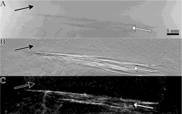
A) Absorption b) Refraction and c) USAXS images of a 1 week explanted hydrogel-tissue sample generated using MIR The underlying tissue (white arrows) produces contrast in all three X-ray property images The hydrogel (black arrows) produces the greatest contrast in the refraction image.
In order to further examine the tissue and hydrogel structure, the two-dimensional refraction images obtained at each tomographic view angle were used to reconstruct CT slices of the samples (Figure 3). In the volumetric refraction CT image, the hydrogel, invading fibrovascular tissue and underlying skeletal muscle could all be clearly identified (Figure 3). Reconstructed absorption and USAXS CT images did not contain significant contrast and detail in hydrogel and soft tissue structure (data not shown). The hydrogel consisted of a speckle pattern likely resulting from the internal porous structure. Skeletal muscle structure could be easily identified in the images, with distinct edges identified at what is likely divisions between individual fascicles. The fibrovascular tissue at the interface between the hydrogel and muscle had a much more heterogeneous structure.
Figure 3.
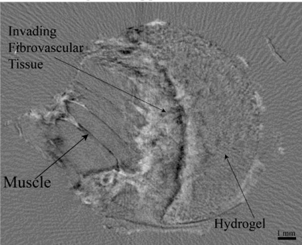
Refraction XPC CT slice of a hydrogel-tissue sample The hydrogel fibrovascular tissue and underlying skeletal muscle can all be clearly identified.
The Refraction CT Slices were rendered to generate 3D volumes of the samples (Figure 4 and Supplemental Video 1). The renderings enable 3D visualization of the entire sample (Figure 4A). They hydrogel could be identified due to its textured appearance. Further, the invading tissue front could be clearly seen (black arrows).
Figure 4.
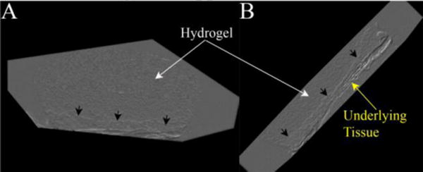
Volume renderings of a hydrogel-tissue sample displaying the 3D structure of the hydrogel (white arrows), invading tissue front (black arrows) and underlying muscle (yellow arrow).
Comparison with Histology
Following XPC imaging, the samples were processed for histology and H&E stained as the gold standard method of analysis. The stained sections were matched to the CT slices for identification and confirmation of the tissue structures observed (Figure 5). XPC imaging allowed identification of similar tissue features seen in the histological images. Fascicles in the underlying muscle could be seen as striations in the XPC refraction image and the bulk structure could be matched between images. The location and bulk shape of the hydrogel was apparent in both images and the pores seen in the histology likely contributed to the texture seen in the hydrogels in the XPC images9.
Figure 5.
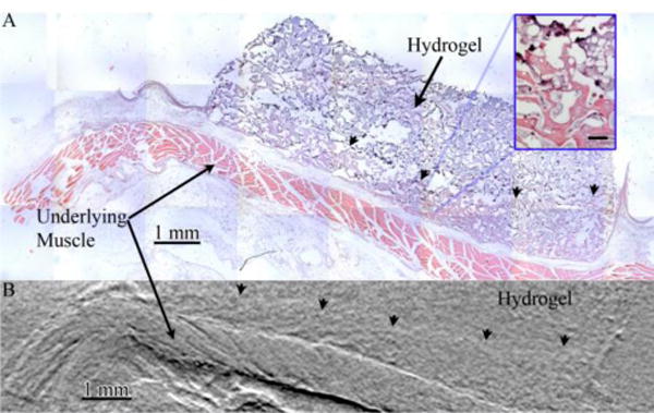
Images of a hydrogel-tissue sample acquired via A) sectioning of the sample followed by H&E staining and widefield optical microscopy and B) digital slices of an XPC refraction CT of whole sample volumes Structure in the underlying muscle is visible in both images as is the front of invading fibrovascular tissue (arrowheads). Inset displayed magnified view of hydrogel (dark purple) and invading fibrovascular tissue Scalebar in inset is 100 μm.
The front edge of tissue invading into the hydrogel structure could be identified in both XPC and histology images (Figure 5). The volume of tissue regenerated is a critical issue in tissue engineering and the depth of invaded tissue represents a critical measurement directly related to the volume of tissue formed. The invasion depth was quantified from histology and XPC images (Figure 6). Both techniques resulted in data showing a general trend of increasing invasion depth with time. In addition, depth did not vary with the concentration of fibrinogen within the hydrogels regardless of analysis methods. Overall, there were no significant difference in the average invasion depths measured using XPC or the gold standard method (quantitative histomorphometry).
Figure 6.
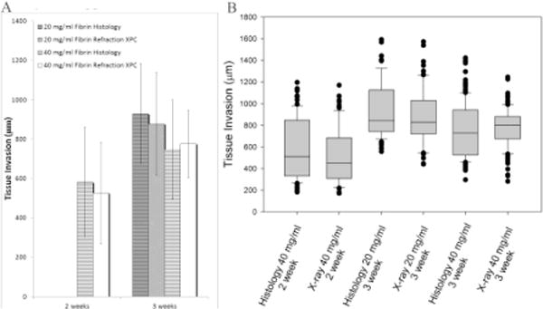
A) Bar graph displaying the mean and standard deviation of tissue invasion depth measured from both histology (striped) and XPC (solid) images B) Box plot displaying median tissue invasion depth along with 10th, 25th, 75th, and 90th percentiles as vertical boxes with error bars for both histology and XPC images XPC provides similar results to the gold standard histological techniques with more precise measurement and less variations.
Discussion
There is a need for techniques that allow three-dimensional, quantitative analysis of hydrogel and soft tissue structure in tissue engineering applications. XPC imaging techniques have been shown to enable visualization of hydrogels based on differences in the X-ray refractive index values of hydrogels and tissue9. In this study, we have expanded on these results, showing that XPC CT imaging allows 3D visualization and quantification of hydrated soft tissues and hydrogels. The XPC images show clear distinction between underlying muscle, invading fibrovascular tissue and the hydrogel without the need for exogenous contrast agents (Figures 4 and 5). Furthermore, when matched to histology, XPC images demonstrated comparable details in both hydrogel and soft tissue structure.
Hydrogels were implanted with varying concentrations of fibrinogen in the pores and harvested at two different time points in order to investigate the role of composition and time on tissue response. The depth of tissue invasion is an important characteristic that relates to the overall volume of engineered tissue generated, which is a critical aspect related to the potential success of a strategy. Depth could be identified and measured in all the samples from XPC refraction data and the results were not different from values measured in corresponding histology. The average depth of tissue invasion measured from the XPC images did not depend on fibrinogen concentration or time for these samples. However, in this study, only a subset of explanted samples from the full larger study were imaged as a proof of concept showing the potential of XPC as a tool for studying hydrogels in tissue engineering applications. Regardless, these findings suggest that the XPC technique would have led to the same conclusions in regards to tissue invasion as previously presented in Jiang et al.23. However, more samples would be needed to provide sufficient power for comparing the different groups as performed with histology in the previous work. Regardless, our results show that XPC can allow analysis comparable to histology but with the added benefit of 3D imaging capabilities and without sectioning and staining the samples.
While the imaging was performed on ex vivo samples at a synchrotron facility, efforts are underway for developing in-lab small animal XPC imagers that could lead to longitudinal in vivo XPC imaging7, 30, 44, 48. Our findings, combined with studies showing in vitro imaging of hydrogel samples2 and full live mice7 with an in-lab XPC system indicate the significant potential for imaging of hydrogels in animals with micro-focus X-ray tube. Depending on the implementation of the in-lab XPC system, the polychromatic nature of the micro-focus X-ray tube can be overcome. With the in-lab analyzer based system a monochromator is utilized to filter the beam48 while for a grating-based system, as source grating can be used to create the necessary degree of coherence7. Additionally, a number of other technical issues will need to be overcome. Specifically, optimized data-acquisition strategies need to be coupled with advanced image reconstruction algorithms in order to overcome the long data-acquisition times and relatively high radiation doses currently required for small animal imaging. Recent results in these areas provide enthusiasm for this possibility19, 20.
PEG hydrogels are being explored for a broad range of biomedical applications. The ability to evaluate the structure of the hydrogels in tissue is critical to evaluating and optimizing their performance. While the PEG hydrogels used in this study were not degradable, in most applications they are made degradable by the introduction of sequences susceptible to hydrolysis or enzymatic cleavage within network crosslinks. Based on their hydrogel contrast within the refraction images observed in this study, it may be possible to track the degradation of degradable PEG hydrogels longitudinally by quantifying overall volume or based on changes in the internal structure.
XPC images also revealed important tissue detail in the underlying skeletal muscle. Detail in the hierarchical structure could be clearly identified, including boundaries between fascicles. This structure is critical to the function of skeletal muscle and may be lost in traumatic or degenerative disease. XPC could be used to identify damaged muscle tissue as well as to evaluate muscle tissue engineering strategies.
The results presented here establish that XPC imaging can reveal features of PEG hydrogels and soft tissues. XPC CT allowed for 3D visualization of hydrogels and quantification of soft tissue invasion. These results suggests that XPC could further benefit tissue engineering by allowing imaging of hydrogels in engineered tissues and monitoring of the local, and integrated, soft tissue response.
Supplementary Material
Acknowledgments
The authors would like to thank Banu Akar and Frederick Doe for staining the samples. This work was supported by grants from the Veterans Administration, National Science Foundation (IIS-1125412, CBET-1263994) and the National Institute of Health (R01EB009715).
References
- 1.Appel AA, Anastasio MA, Larson JC, Brey EM. Imaging challenges in biomaterials and tissue engineering. Biomaterials. 2013;34:6615–6630. doi: 10.1016/j.biomaterials.2013.05.033. [DOI] [PMC free article] [PubMed] [Google Scholar]
- 2.Appel A, Larson JC, Garson AB, 3rd, Guan H, Zhong Z, Nguyen BN, Fisher JP, Anastasio MA, Brey EM. X-ray phase contrast imaging of calcified tissue and biomaterial structure in bioreactor engineered tissues. Biotechnol Bioeng. 2015;112:612–620. doi: 10.1002/bit.25467. [DOI] [PubMed] [Google Scholar]
- 3.Appel A, Larson JC, Somo S, Zhong Z, Spicer PP, Kasper FK, Garson AB, 3rd, Zysk AM, Mikos AG, Anastasio MA, Brey EM. Imaging of poly(alpha-hydroxy-ester) scaffolds with X-ray phase-contrast microcomputed tomography. Tissue engineering Part C Methods. 2012;18:859–865. doi: 10.1089/ten.tec.2012.0123. [DOI] [PMC free article] [PubMed] [Google Scholar]
- 4.Arfelli F, Assante M, Bonvicini V, Bravin A, Cantatore G, Castelli E, DallaPalma L, Di Michiel M, Longo R, Olivo A, Pani S, Pontoni D, Poropat P, Prest M, Rashevsky A, Tromba G, Vacchi A, Vallazza E. FZanconati Low-dose phase contrast x-ray medical imaging. Physics in Medicine and Biology. 1998;43:2845–2852. doi: 10.1088/0031-9155/43/10/013. [DOI] [PubMed] [Google Scholar]
- 5.Artzi N, Oliva N, Puron C, Shitreet S, Artzi S, bon Ramos A, Groothuis A, Sahagian G, Edelman ER. In vivo and in vitro tracking of erosion in biodegradable materials using non-invasive fluorescence imaging. Nature Materials. 2011;10:704–709. doi: 10.1038/nmat3095. [DOI] [PMC free article] [PubMed] [Google Scholar]
- 6.Bal U, Andresen V, Baggett B. UUtzinger Intravital confocal and two-photon imaging of dual-color cells and extracellular matrix mimics. Microsc Microanal. 2013;19:201–212. doi: 10.1017/S1431927612014080. [DOI] [PMC free article] [PubMed] [Google Scholar]
- 7.Bech M, Tapfer A, Velroyen A, Yaroshenko A, Pauwels B, Hostens J, Bruyndonckx P, Sasov A, Pfeiffer F. In-vivo dark-field and phase-contrast x-ray imaging. Scientific Reports. 2013;3:3209. doi: 10.1038/srep03209. [DOI] [PMC free article] [PubMed] [Google Scholar]
- 8.Brankov J, Wernick MN, Yang Y, Li J, Muehleman C, Zhong Z, Anastasio MA. A computed tomography implementation of multiple-image radiography. Medical Physics. 2006;33:278. doi: 10.1118/1.2150788. [DOI] [PubMed] [Google Scholar]
- 9.Brey E, Appel A, Chiu YC, Zhong Z, Cheng MH, Engel H, Anastasio MA. X-ray imaging of poly(ethylene glycol) hydrogels without contrast agents. Tissue engineering Part C Methods. 2010;16:1597–1600. doi: 10.1089/ten.tec.2010.0150. [DOI] [PMC free article] [PubMed] [Google Scholar]
- 10.Cedola A, Campi G, Pelliccia D, Bukreeva I, Fratini M, Burghammer M, Rigon L, Arfelli F, Chang Chen R, Dreossi D, Sodini N, Mohammadi S, Tromba G, Cancedda R, Mastrogiacomo M. Three dimensional visualization of engineered bone and soft tissue by combined x-ray micro-diffraction and phase contrast tomography. Physics in medicine and biology. 2014;59:189–201. doi: 10.1088/0031-9155/59/1/189. [DOI] [PubMed] [Google Scholar]
- 11.Chan K, Liu G, Song X, Kim H, Yu T, Arifin DR, Gilad AA, Hanes J, Walczak P, van Zijl PC, Bulte JW, McMahon MT. MRI-detectable pH nanosensors incorporated into hydrogels for in vivo sensing of transplanted-cell viability. Nature Materials. 2013;12:268–275. doi: 10.1038/nmat3525. [DOI] [PMC free article] [PubMed] [Google Scholar]
- 12.Chan K, Liu G, van Zijl PC, Bulte JW, McMahon MT. Magnetization transfer contrast MRI for non-invasive assessment of innate and adaptive immune responses against alginate-encapsulated cells. Biomaterials. 2014;35:7811–7818. doi: 10.1016/j.biomaterials.2014.05.057. [DOI] [PMC free article] [PubMed] [Google Scholar]
- 13.Chiu Y, Brey EM, Perez-Luna VH. A study of the intrinsic autofluorescence of poly (ethylene glycol)-co-(L-lactic acid) diacrylate. Journal of fluorescence. 2012;22:907–913. doi: 10.1007/s10895-011-1029-6. [DOI] [PubMed] [Google Scholar]
- 14.Chiu Y, Cheng MH, Engel H, Kao SW, Larson JC, Gupta S, Brey EM. The role of pore size on vascularization and tissue remodeling in PEG hydrogels. Biomaterials. 2011;32:6045–6051. doi: 10.1016/j.biomaterials.2011.04.066. [DOI] [PubMed] [Google Scholar]
- 15.Chou C-Y, Anastasio MA, Brankov JG, Wernick MN, Brey EM, Connor DM, Zhong Z. An extended diffraction-enhanced imaging method for implementing multiple-image radiography. Physics in medicine and biology. 2007;52:1923–1945. doi: 10.1088/0031-9155/52/7/011. [DOI] [PubMed] [Google Scholar]
- 16.E Chung, Nam SY, Ricles LM, Emelianov S, Suggs L. Evaluation of gold nanotracers to track adipose-derived stem cells in a PEGylated fibrin gel for dermal tissue engineering applications. International Journal of Nanomedicine. 2013;8:325–336. doi: 10.2147/IJN.S36711. [DOI] [PMC free article] [PubMed] [Google Scholar]
- 17.Edmunds K, Gargiulo P. Imaging approaches in functional assessment of implantable myogenic biomaterials and engineered muscle tissue. European Journal of Translational Myology - Basic Applied Myology. 2015;25:63–76. doi: 10.4081/ejtm.2015.4847. [DOI] [PMC free article] [PubMed] [Google Scholar]
- 18.Francis-Sedlak ME, Uriel S, Larson JC, Greisler HP, Venerus DC, Brey EM. Characterization of type I collagen gels modified by glycation. Biomaterials. 2009;30:1851–1856. doi: 10.1016/j.biomaterials.2008.12.014. [DOI] [PubMed] [Google Scholar]
- 19.Guan H, Xu Q, Garson A, Anastasio MA. Depth resolution properties of in-line X-ray phase-contrast tomosynthesis. 2014;9033:90330H. [Google Scholar]
- 20.Guan H, Xu Q, Garson AB, 3rd, Anastasio MA. Boundary-enhancement in propagation-based x-ray phase-contrast tomosynthesis improves depth position characterization. Physics in medicine and biology. 2015;60:N151–165. doi: 10.1088/0031-9155/60/8/N151. [DOI] [PubMed] [Google Scholar]
- 21.Gudur M, Rao RR, Peterson AW, Caldwell DJ, Stegemann JP, Deng CX. Noninvasive quantification of in vitro osteoblastic differentiation in 3D engineered tissue constructs using spectral ultrasound imaging. PLoS One. 2014;9:e85749. doi: 10.1371/journal.pone.0085749. [DOI] [PMC free article] [PubMed] [Google Scholar]
- 22.Izadifar Z, Chapman LD, Chen X. Computed tomography diffraction-enhanced imaging for in situ visualization of tissue scaffolds implanted in cartilage. Tissue engineering Part C Methods. 2014;20:140–148. doi: 10.1089/ten.TEC.2013.0138. [DOI] [PubMed] [Google Scholar]
- 23.Jiang B, Waller TM, Larson JC, Appel AA, Brey EM. Fibrin-loaded porous poly (ethylene glycol) hydrogels as scaffold materials for vascularized tissue formation. Tissue Engineering Part A. 2012;19:224–234. doi: 10.1089/ten.tea.2012.0120. [DOI] [PMC free article] [PubMed] [Google Scholar]
- 24.Karfeld-Sulzer LS, Waters EA, Kohlmeir EK, Kissler H, Zhang X, Kaufman DB, Barron AE, Meade TJ. Protein polymer MRI contrast agents: Longitudinal analysis of biomaterials in vivo. Magnetic resonance in medicine: official journal of the Society of Magnetic Resonance in Medicine/Society of Magnetic Resonance in Medicine. 2011;65:220–228. doi: 10.1002/mrm.22587. [DOI] [PMC free article] [PubMed] [Google Scholar]
- 25.Kim K, Jeong CG, Hollister SJ. Non-invasive monitoring of tissue scaffold degradation using ultrasound elasticity imaging. Acta Biomaterialia. 2008;4:783–790. doi: 10.1016/j.actbio.2008.02.010. [DOI] [PMC free article] [PubMed] [Google Scholar]
- 26.Kim S, Lee JH, Hyun H, Ashitate Y, Park G, Robichaud K, Lunsford E, Lee SJ, Khang G, Choi H. Near-Infrared Fluorescence Imaging for Noninvasive Trafficking of Scaffold Degradation. Scientific Reports. 2013;3:1–7. doi: 10.1038/srep01198. [DOI] [PMC free article] [PubMed] [Google Scholar]
- 27.Lammers G, Verhaegen PD, Ulrich MM, Schalkwijk J, Middelkoop E, Weiland D, Nillesen ST, Van Kuppevelt TH, Daamen WF. An overview of methods for the in vivo evaluation of tissue-engineered skin constructs. Tissue engineering Part B Reviews. 2011;17:33–55. doi: 10.1089/ten.TEB.2010.0473. [DOI] [PubMed] [Google Scholar]
- 28.Lewis R. Medical phase contrast x-ray imaging: current status and future prospects. Physics in medicine and biology. 2004;49:3573–3583. doi: 10.1088/0031-9155/49/16/005. [DOI] [PubMed] [Google Scholar]
- 29.Liang Y, Bar-Shir A, Song X, Gilad AA, Walczak P, Bulte JW. Label-free imaging of gelatin-containing hydrogel scaffolds. Biomaterials. 2015;42:144–150. doi: 10.1016/j.biomaterials.2014.11.050. [DOI] [PMC free article] [PubMed] [Google Scholar]
- 30.Lim H, Park Y, Cho H, Je U, Hong D, Park C, Woo T, Lee M, Kim J, Chung N. Experimental setup and the system performance for single-grid-based phase-contrast x-ray imaging (PCXI) with a microfocus x-ray tube. Optics Communications. 2015;348:85–89. [Google Scholar]
- 31.Mercado KP, Helguera M, Hocking DC, Dalecki D. Noninvasive Quantitative Imaging of Collagen Microstructure in Three-Dimensional Hydrogels Using High-Frequency Ultrasound. Tissue engineering Part C Methods. 2015 doi: 10.1089/ten.tec.2014.0527. [DOI] [PMC free article] [PubMed] [Google Scholar]
- 32.Mollenhauer J, Aurich ME, Zhong Z, Muehleman C, Cole AA, Hasnah M, Oltulu O, Kuettner KE, Margulis A, Chapman LD. Diffraction-enhanced X-ray imaging of articular cartilage. Osteoarthritis Cartilage. 2002;10:163–171. doi: 10.1053/joca.2001.0496. [DOI] [PubMed] [Google Scholar]
- 33.Nam S, Ricles LM, Suggs LJ, Emelianov SY. Imaging strategies for tissue engineering applications. Tissue engineering Part B Reviews. 2015;21:88–102. doi: 10.1089/ten.teb.2014.0180. [DOI] [PMC free article] [PubMed] [Google Scholar]
- 34.Paganin DM. Coherent X-ray Optics. Oxford University Press; 2006. p. 411. [Google Scholar]
- 35.Ramaswamy S, Wang DA, Fishbein KW, Elisseeff JH, Spencer RG. An analysis of the integration between articular cartilage and nondegradable hydrogel using magnetic resonance imaging. Journal of Biomedical Materials Research Part B: Applied Biomaterials. 2006;77:144–148. doi: 10.1002/jbm.b.30404. [DOI] [PubMed] [Google Scholar]
- 36.Sciarretta F 5 to 8 years follow-up of knee chondral defects treated by PVA-H hydrogel implants. European Review for Medical and Pharmacological Sciences. 2013;17:3031–3038. [PubMed] [Google Scholar]
- 37.Smith LE, Bonesi M, Smallwood R, Matcher SJ, MacNeil S. Using swept-source optical coherence tomography to monitor the formation of neo-epidermis in tissue-engineered skin. Journal of tissue engineering and regenerative medicine. 2010;4:652–658. doi: 10.1002/term.281. [DOI] [PubMed] [Google Scholar]
- 38.Sumner JP, Hardie RJ, Henningson JN, Drees R, Markel MD, Bjorling D. Evaluation of submucosally injected polyethylene glycol-based hydrogel and bovine cross-linked collagen in the canine urethra using cystoscopy magnetic resonance imaging and histopathology. Vet Surg. 2012;41:655–663. doi: 10.1111/j.1532-950X.2012.01005.x. [DOI] [PubMed] [Google Scholar]
- 39.Traoré A, Woerly S, Doan V, Marois Y, Guidoin R. In vivo magnetic resonance imaging and relaxometry study of a porous hydrogel implanted in the trapezius muscle of rabbits. Tissue engineering. 2000;6:265–278. doi: 10.1089/10763270050044443. [DOI] [PubMed] [Google Scholar]
- 40.van Zijl PC, Yadav NN. Chemical exchange saturation transfer (CEST): what is in a name and what isn’t? Magnetic resonance in medicine: official journal of the Society of Magnetic Resonance in Medicine/Society of Magnetic Resonance in Medicine. 2011;65:927–948. doi: 10.1002/mrm.22761. [DOI] [PMC free article] [PubMed] [Google Scholar]
- 41.Wang Z, Pan H, Yuan Z, Liu J, Chen W, Pan Y. Assessment of Dermal Wound Repair after Collagen Implantation with Optical Coherence Tomography. Tissue engineering Part C Methods. 2008;14:35–45. doi: 10.1089/tec.2007.0285. [DOI] [PubMed] [Google Scholar]
- 42.Werkmeister E, Dumas D, de Isla N, Marchal L, Stoltz JF. Interest of Multimodal Imaging in Tissue Engineering. Bio-Medical Materials and Engineering. 2008;18:329–333. [PubMed] [Google Scholar]
- 43.Wernick MN, Wirjadi O, Chapman D, Zhong Z, Galatsanos NP, Yang Y, Brankov JG, Oltulu O, Anastasio MA, Muehleman C. Multiple-image radiography. Physics in medicine and biology. 2003;48:3875–3895. doi: 10.1088/0031-9155/48/23/006. [DOI] [PubMed] [Google Scholar]
- 44.Yoon K-H, Ryu JH, Jung CW, Ryu CW, Kim YJ, Kwon YM, Park M, Cho S, Chon KS. Differential X-ray phase-contrast imaging with a grating interferometer using a laboratory X-ray micro-focus tube. Journal of the Korean Physical Society. 2014;65:2111–2116. [Google Scholar]
- 45.Yuan Z, Zakhaleva J, Ren H, Liu J, Chen W, Pan Y. Noninvasive and high-resolution optical monitoring of healing of diabetic dermal excisional wounds implanted with biodegradable in situ gelable hydrogels. Tissue Eng Part C. 2010;16:237–247. doi: 10.1089/ten.tec.2009.0152. [DOI] [PMC free article] [PubMed] [Google Scholar]
- 46.Zhang Y, Sun Y, Yang X, Hilborn J, Heerschap A, Ossipov DA. Injectable in situ forming hybrid iron oxide-hyaluronic acid hydrogel for magnetic resonance imaging and drug delivery. Macromol Biosci. 2014;14:1249–1259. doi: 10.1002/mabi.201400117. [DOI] [PubMed] [Google Scholar]
- 47.Zhong Z, Thomlinson W, Chapman D, Sayers D. Implementation of diffraction-enhanced imaging experiments: at the NSLS and APS. Nuclear Instruments and Methods in Physics Research Section A: Accelerators Spectrometers Detectors and Associated Equipment. 2000;450:556–567. [Google Scholar]
- 48.Zhou W, Majidi K, Brankov JG. SPIE Optical Engineering+ Applications. International Society for Optics and Photonics; 2014. Phase contrast imaging using a micro focus x-ray source; pp. 92070U–92070U–92078. [Google Scholar]
- 49.Zhu N, Chapman D, Cooper D, Schreyer DJ, Chen X. X-ray diffraction enhanced imaging as a novel method to visualize low-density scaffolds in soft tissue engineering. Tissue engineering Part C Methods. 2011;17:1071–1080. doi: 10.1089/ten.tec.2011.0102. [DOI] [PubMed] [Google Scholar]
- 50.Ziv K, Nuhn H, Ben-Haim Y, Sasportas LS, Kempen PJ, Niedringhaus TP, Hrynyk M, Sinclair R, Barron AE, Gambhir SS. A tunable silk-alginate hydrogel scaffold for stem cell culture and transplantation. Biomaterials. 2014;35:3736–3743. doi: 10.1016/j.biomaterials.2014.01.029. [DOI] [PMC free article] [PubMed] [Google Scholar]
Associated Data
This section collects any data citations, data availability statements, or supplementary materials included in this article.


