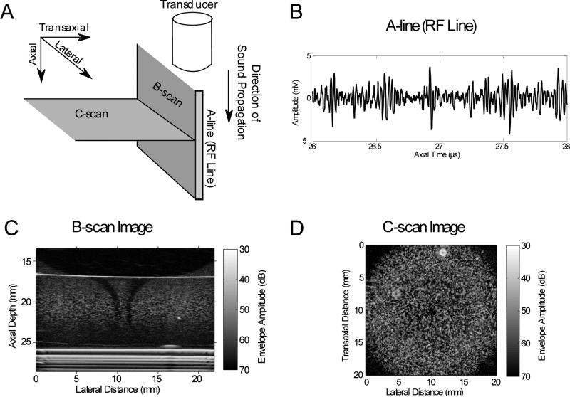
Figure 1. Ultrasound imaging modes.
(A) Schematic of the orientations of common ultrasound imaging modes (i.e., A-line, B-scan, and C-scan) with respect to the direction of sound propagation. (B) A plot of an A-line (RF line) displayed as the amplitude of the backscattered ultrasound echo signal as a function of time. (C) B-scan imaging planes are parallel to the direction of sound propagation. Shown is a B-scan image of a cylindrical collagen hydrogel embedded with fibroblasts (generated using methods as described previously16). (D) C-scan imaging planes are perpendicular to the direction of sound propagation. Shown is a C-scan image of a cylindrical collagen hydrogel embedded with fibroblasts (generated using methods as described previously18).

