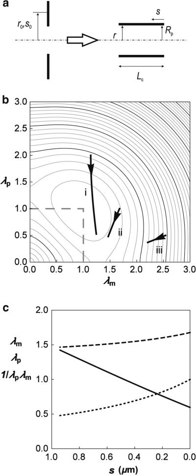
Fig. 3.
Skeleton deformation due to transformation from annulus to cylinder. a Side view of the deformation. s0 is the contour along the undeformed skeleton and s the contour along the deformed skeleton. The radial distance from the axis of symmetry in the undeformed state is r0 and in the deformed state, r. The areas of the cylinder and the annulus are equal (5.9 μm2). b The variation in the reduced energy of the deformed skeleton with position, s, is illustrated by the solid curves overlaid on a contour depiction of the reduced strain energy u(λm, λp) as a function of the extension ratios λm and λp. The inner radius of the annulus is taken to be Rp/2 (curve i), Rp (curve ii) and 2Rp (curve iii) where Rp = 0.56 μm. Arrows indicate the direction of increasing arc length s. c The extension ratios λm (dashed line) and λp (dotted line) and the reduced bond area density 1/λmλp (solid line) as a function of arc length s for the case where the initial inner radius of the annulus is Rp. In keeping with the diagram shown in a, s increases from right to left.

