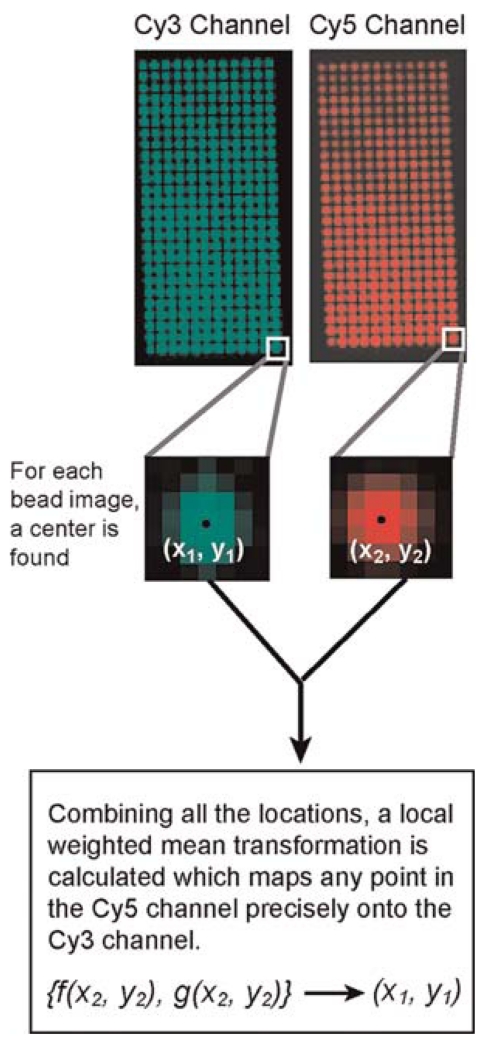
FIGURE 3.
Explanation of the data collected and analysis that determines the transformation from one channel to the other. A bead that emits broadly so that it can be seen in each imaging channel is moved in a grid-like manner through the field of view. (Top panels) Resulting grid. Each bead is localized in both channels, which produces a pair of control points, {(x1, y1), (x2, y2)} (center). All of the pairs of control points contribute to the calculation of an LWM transformation from one imaging channel to the other (bottom).

