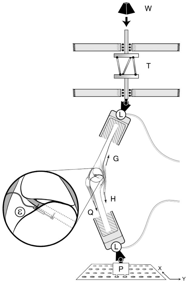
Figure 1.
Schematic diagram of the test apparatus showing how a weight (W) dropped from a fixed height onto the torsional transformer device (T) applied impulsive compression and axial torque to the distal tibia of an inverted knee specimen. For the varus or valgus loading condition, the knee specimen was initially adducted or abducted by translating the bottom plate (P) in ±x direction. The two 6 degrees of freedom load cells (L) measured the 3 components of force and moment applied to the knee specimen. Quadriceps (Q), hamstrings (H), and gastrocnemius (G) forces using 1 degree of freedom transducers. A miniature displacement transducer (ε) implanted on the surface of the anteromedial bundle of the ACL measured relative strain. (Reprinted with permission from Oh et al.35)

