
Figure 3. Schematic of pattern switching ‘O→K→O' by phase-selective entrainment.

(a) Natural frequencies for four spatially distributed oscillator clusters of sizes (N1, N2, N3, N4)=(7, 7, 3, 3) in an ascending order: ω1<ω2<ω3<ω4. Cluster 1 contains electrodes n=1 to 7 (blue), cluster 2 contains n=8 to 14 (cyan), cluster 3 contains n=15 to 17 (yellow) and cluster 4 contains n=18 to 20 (red). Items b to d depict snapshots of phase patterns at the forcing phase θ=0 (top row), the description of the phases on a unit circle (middle row), and a sketch of the interaction function (bottom row). Phase assignment for: (b): Pattern ‘O': 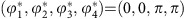 . (c): Precursor of pattern ‘K':
 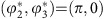 . (d): Pattern ‘K':
 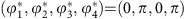 .
.