
Figure 4. Pattern switching experiment ‘O→K→O' on an array of electrochemical oscillators.

Left: current oscillations with the control signal above. Right: oscillator phases on a unit circle and a snapshot of spatial phase assignment at a time ts. (a): Current oscillations with no control and mean natural frequencies for four electrode clusters (N1, N2, N3, N4)=(7, 7, 3, 3) of (ω1, ω2, ω3, ω4)=(0.390, 0.406, 0.427, 0.442) Hz at ts=92 s. Phase assignment with forcing at Ω=0.408 Hz for: (b): Pattern ‘O': 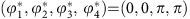 , at ts=351 s. (c): Precursor of pattern ‘K':
 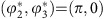 , at ts=570 s. (d): Pattern ‘K':
 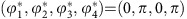 , at ts=721 s. (e): Same as item (b) with ts=1,001 s.