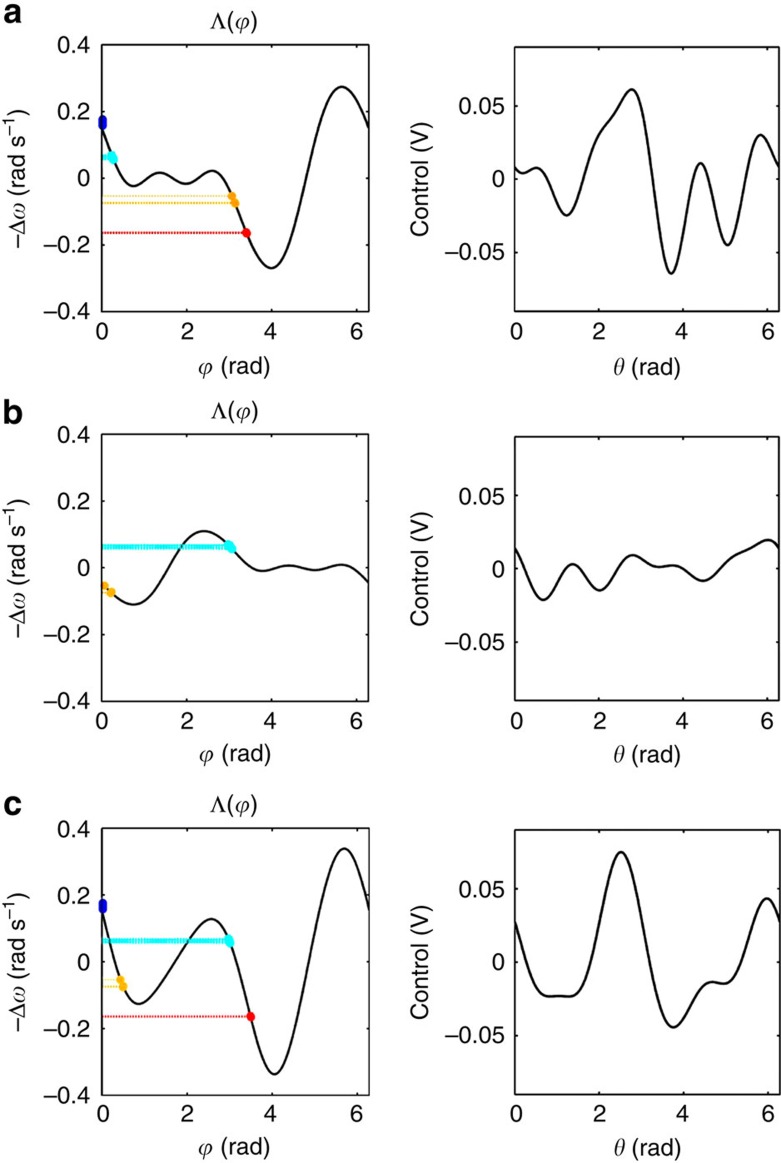
Figure 6. Interaction function and control waveform for pattern switching ‘O→K→O' described in Fig. 4.
Left: the best approximation to the desired interaction function; Right: one cycle of the resulting control waveform, obtained using the control design procedure described in section ‘Control of pattern transitions in an ensemble', which is applied to entrain the electrochemical oscillators. The ensemble is grouped into four clusters of quantities (N1, N2, N3, N4)=(7, 7, 3, 3). Cluster 1 for oscillators j=1 to 7 (blue), cluster 2 for j=8 to 14 (cyan), cluster 3 for j=15 to 17 (yellow) and cluster 4 for j=18 to 20 (red). Phase assignment for: (a): Pattern ‘O':  . (b): Precursor of pattern ‘K':
  . (c): Pattern ‘K':
  .
.

