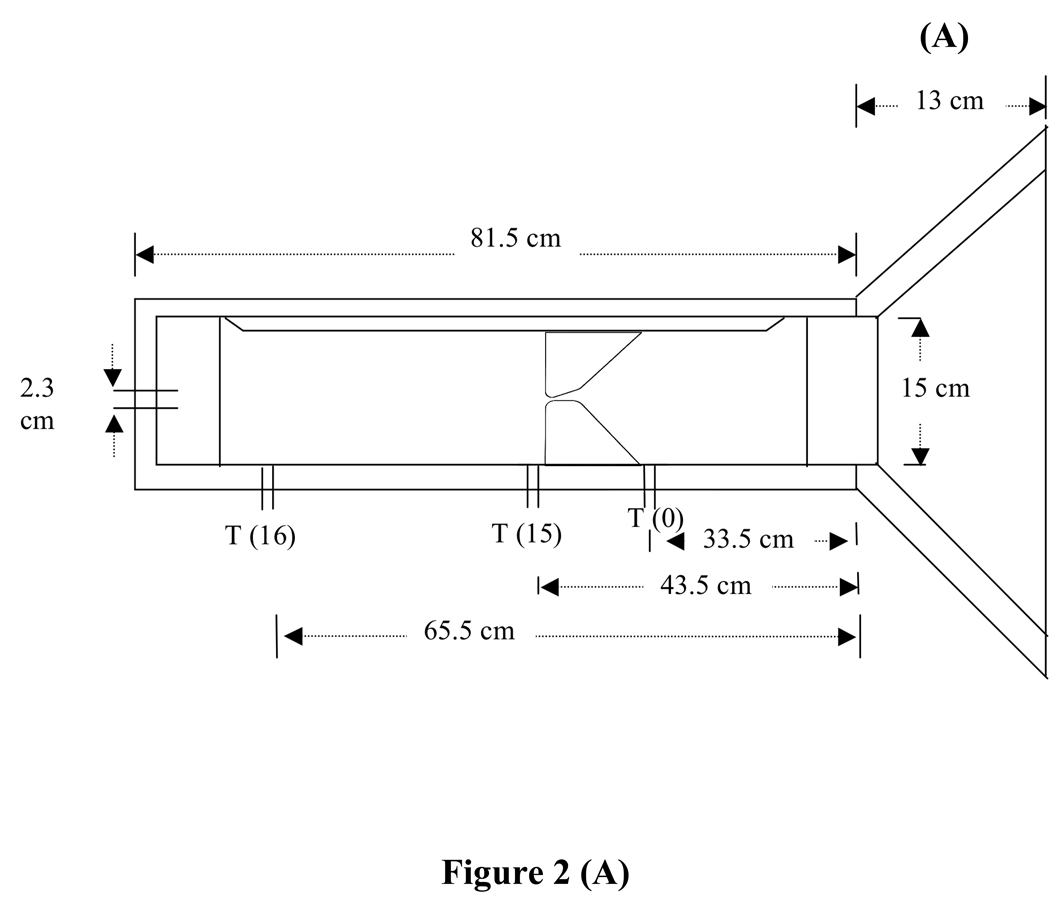
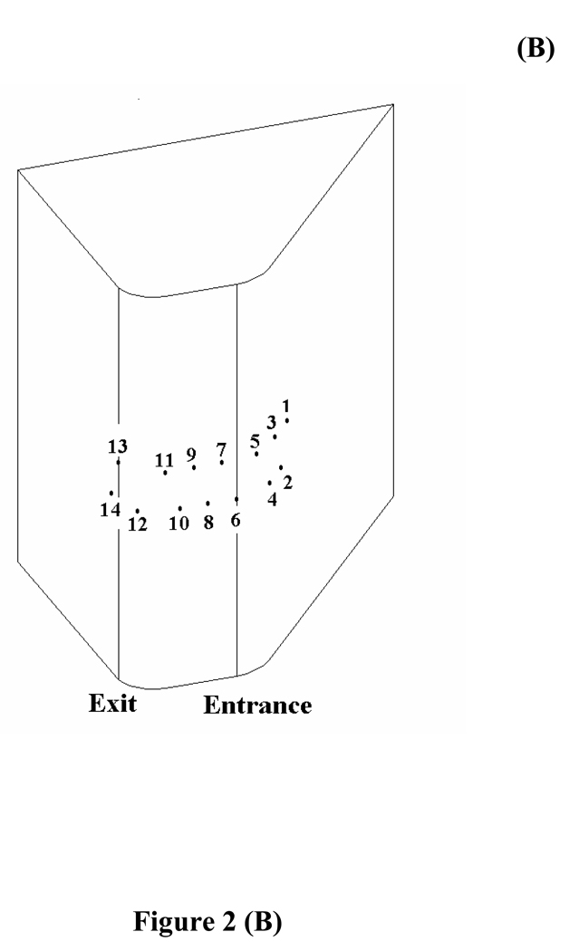
FIG. 2.
(A) Schematic diagram of the wind tunnel used for the hemilarynx experiments. The glottal diameter is the minimum separation between the vocal fold inserts. Because of the converging glottal angle between the medial surfaces shown in the schematic, the minimum separation is near the glottal exit. (B) Locations of the 14 pressure taps on one of the vocal fold inserts. (from Fig. 5 of Ref. 10)


