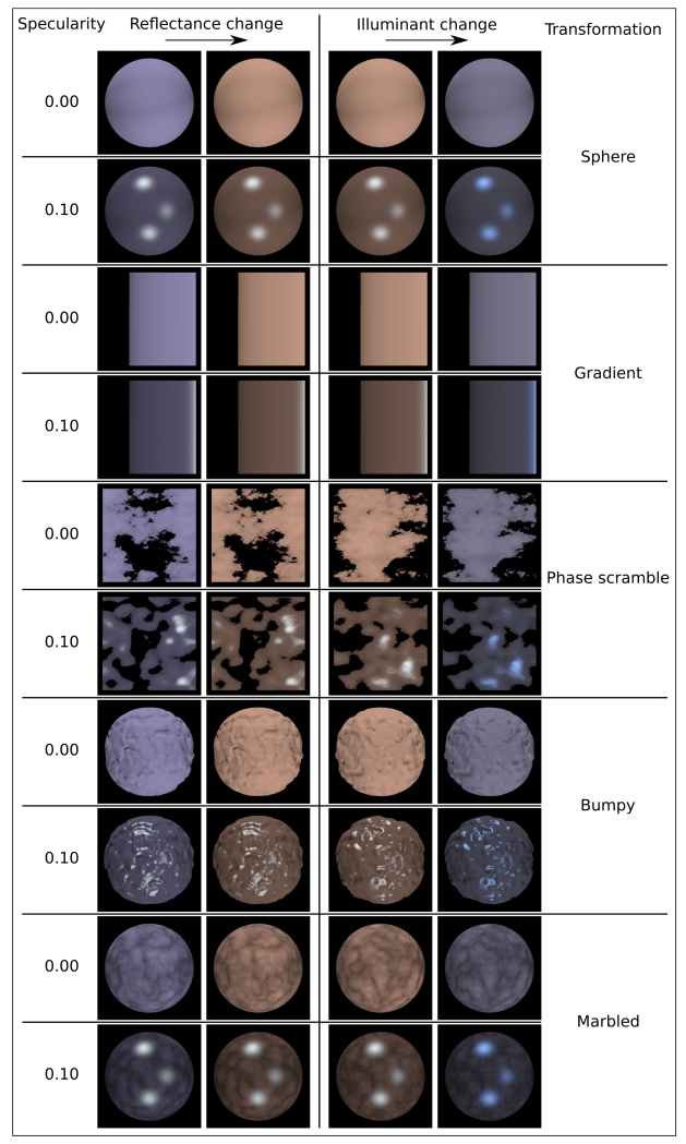
Fig. 4.
Examples of images from the stimulus animations used in our experiments. The left two columns show the first and final images from an animation of a reflectance change, while the right two columns show the first and final images from an animation of an illuminant change. To aid comparison of these stimulus types, the reflectance and illuminant for the final frame of the reflectance-change example are the same as the reflectance and illuminant for the first frame in the illuminant-change example. Pairs of rows show images for the lowest and highest specularities (0.00 and 0.10 respectively) for the Sphere, Gradient, Scrambled conditions of Experiment 1, and the Bumpy and Marbled conditions of Experiment 2. Note that the color changes in the zero specularity condition are identical for reflectance and illuminant changes, despite the difference in the source of this change. Color reproduction in this figure will not be accurate.

