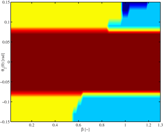
Figure 10. Limit behaviour of system (7) with input (6) as a function of the initial condition θ2(0) of pendulum two and the damping in the coupling structure, determined by β, see Eq. (30).

The colors indicate the type of behaviour the system exhibits after 25000 [s]. Yellow: in-phase synchronization, cyan: anti-phase synchronization, brown: the initial condition of pendulum two is not enough to activate its escapement mechanism and consequently, pendulum two comes to stand still, blue: the pendula exhibit frequency synchronization, but the phase difference is neither 0 nor π. For all cases, the initial condition of pendulum one has been fixed to θ1(0) = 0.15 [rad].
