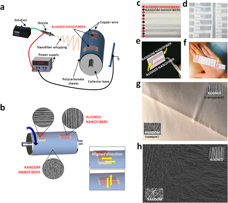
Figure 1.
(a) Schematic illustration of fabrication for the controlled design of aligned and randomly oriented nanofibers (b) Schematic illustration of the direction of the nanofiber alignment influenced by the cellophane tape attachment (c) Macrograph of the mat with randomly oriented nanofibers with aligned nanofibers at regular intervals (d) Single mat with multiple angled U shape aligned nanofibrous mat (e) Single angled U shape aligned nanofibrous mat (f) Different sized angled U shape aligned nanofibrous mat (g) Macrograph of border of aligned and random nanofibrous mat (h) SEM image of border of aligned and random nanofibrous mat.

