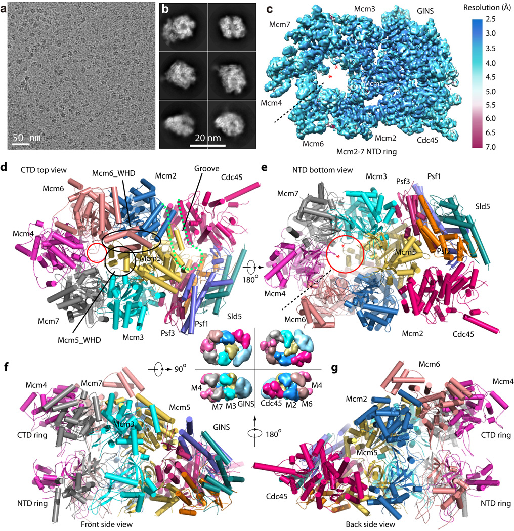
Figure 1. Cryo-EM and overall structure of the S. cerevisiae CMG complex.
(a) A typical motion-corrected raw image of frozen CMG particles recorded on a direct detector. (b) Selected six 2D averages representing the particles in different views. (c) 3D cryo-EM map of CMG color coded by local resolution. Overall resolution is 3.7 Å. This density map includes Cdc45-GINS-Mcm2-7 NTD ring. The two red asterisks mark the hairpin loop in the NTD OB-subdomain of Mcm4 and Mcm7 that protrude into the axial channel. (d–g), Cartoon view of the full-length atomic model of CMG conformer I as viewed from the CTD motor ring (d), NTD bottom (e), Front side (f) and back side (g). The dashed black line in (c, e) marks the smaller interface between NTDs of Mcm4 and Mcm6. The dashed magenta curve in (d) marks the groove between Cdc45 and Mcm2-Mcm5. The smaller red circle in (d) marks the constricted opening (10 Å) at the CT motor ring. The large red circle in (e) marks the 20 Å channel opening at the bottom. The black circle and the oval in (d) mark the WHD of Mcm5 and Mcm6, respectively. The central four surface representations of CMG between panels (d)–(g) are an aid to understanding the high resolution structures. They are lower resolution EM map of CMG (EMDB 6463)16.

