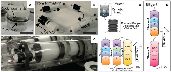
Figure 2.
Overview of the FLOCS experiments used in this study. (A) Polycarbonate cassettes containing >250 μm crushed mineral substrates, with ventilated caps and o-ring seal on outside. (B) The FLOCS (PVC) sleeves deployed in the negative control at Hole U1301B connected in series illustrating direction of fluid flow. (C) The FLOCS sleeves mated to the Teflon tubing coils and osmotic pumps inside the plates to be attached to the wellhead. (D) Schematic of FLOCS experimental design deployed at Hole U1301A, where substrates are listed in order of fluid flow: GB, Glass wool and Basalt; P, Pyrite; B, Hole U1301B Basalt; H, Hematite; MC*, cm2 mineral chips; G, Goethite (*denotes substrates that were not used in this study and allocated for other analyses). (E) Hole U1301A passive flow (no OSMO pump) deployment labeled with identical substrate abbreviations as (D).

