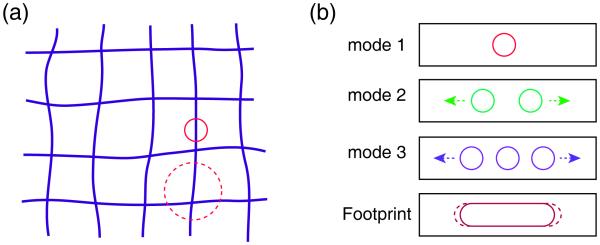
Figure 4.
Challenges of distortion correction in the combined fly-scan ptychographic and fluorescence imaging. (a) Schematic of scans with distortion using small probe (circle) and big probe (dash circle). The big probe covers more features of the sample, allowing for more probe overlaps at each specimen position for improved distortion correction. However, the small probe is better for fluorescence imaging. (b) Schematic of reconstructed probes in fly-scan ptychography. The scan speed in fly scan is assumed to be constant, which produces a uniform probe footprint (brown rounded rectangle) for each diffraction pattern. In real experiments the possibility of non-constant scan speed might result in various probe footprints (dash rounded rectangle) which correspondingly have a series of different probe modes; this would further complicate the task of correcting for probe position errors.

