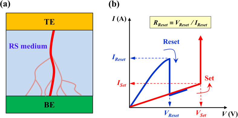
Figure 1. Schematic diagram for filamentary channels in a RS device and unipolar RS characteristics.
(a) Schematic of an electrode-binary oxide-electrode RS device with a tree structure of filamentary conducting channels embedded inside the RS insulating medium. (b) Typical unipolar-type resistive switching I–V characteristics of a metal-binary oxide-metal RS device. The switching resistance R is defined as the ratio of the switching voltage to the switching current.

