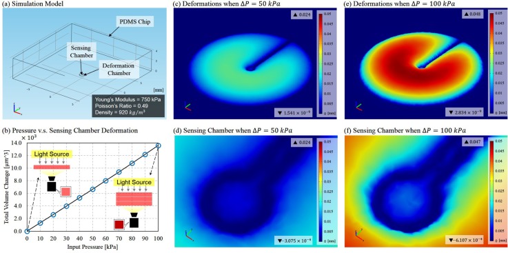
FIG. 2.
FEM simulation results. (a) The model built for the simulation. (b)The relation between the applied pressure and the total deformation over the sensing chamber. (c) The deformation when a pressure of 50 kPa is applied in the deformation chamber. (d) The deformation around the sensing chamber when P = 50 kPa. (e) The deformation when a pressure of 100 kPa is applied in the deformation chamber. (f) The deformation around the sensing chamber when P = 100 kPa.

