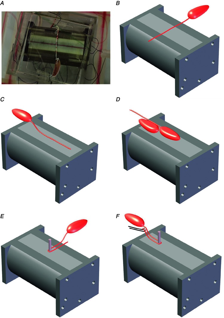
Figure 4. Experimental configurations using the cane toad sciatic–gastrocnemius nerve–muscle preparation .

A, photograph of the bipole device underneath the bath housing the nerve–muscle preparation, aligned perpendicular to the bipole axis (Expt 1). B–F, schematic diagrams. B, nerve perpendicular to the bipole axis as in A (Expt 1). C, nerve parallel to the bipole axis, muscle raised onto a platform (Expt 5). D, nerve–muscle parallel to the bipole axis, muscle at its centre dorsal side down and nerve raised (Expt 8); a second muscle with nerve severed is centred on the point of highest parallel electric field. E, nerve wrapped one half‐turn around an insulating pillar positioned at the device centre, nerve approaching pillar perpendicular to the axis (Expt 12). F, test of blocking of action potential propagation created near the ligated end of the nerve by electrical stimulation (Expt 19).
