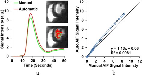
Fig. 4.

Comparison of AIF computed from automatically detected LV pixels vs. a manually selected ROI. The selected regions and the AIF curve measured from them are shown in a. Note how the automatically selected region (red pixels) excludes approximately three darker pixels included in the manual ROI (green ring), and includes other bright pixels outside the ring. The automatic AIF, as a result, displays a higher peak value and upslope, while maintaining similar time to peak and full-width at half maximum. Correlation of the manual and automatic AIF curves is shown in b. Despite the high correlation indicated, the differences in peak signal intensity give the trend line a larger slope (>1)
