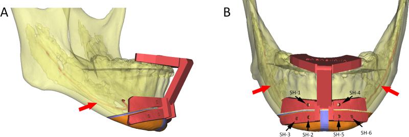
Fig. 1.
(A) The upper portion of the cutting guide is designed like a dental splint. The lower portion of the guide is designed to indicate the cutting lines and the trajectory of the cutting plane (indicated by the thickness of the cutting guide). (B) Six screw-hole drilling guides (black dots) are designed on both sides of the osteotomy cutting lines to provide stable bony reference landmarks. The inferior alveolar nerve (red arrow) is marked on the 3D model. (Chin segments are marked in orange; bony collisions for ostectomy during the repositioning are marked in blue; SH: screw hole.)

