
Figure 3.
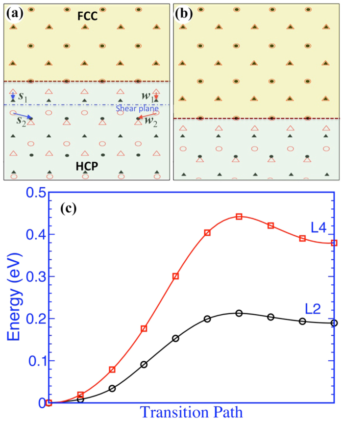
(a,b) Topological models illustrating growth of fcc band. Two sets of displacements, s1 and w1, and s2 and w2, correspond to two opposite-signed two-layer disconnections (shear-shuffle). (c) The change in the potential energy with respect to the transition path. L2 represents a two-layer shear-shuffle and L4 represents a four-layer pure-shuffle. The two crystals adopt the orientation relation described as the x-axis along the 〈 〉hcp and 〈
 〉fcc, the y-axis along 〈
 〉hcp and 〈110〉fcc, and the z-axis along 〈0001〉hcp and 〈001〉fcc.