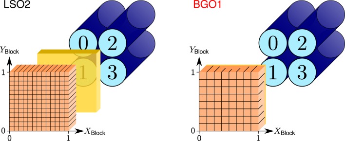
Figure 6.
Sketch of the LSO2 (left) and BGO1 (right) block detectors with the PMT numbering convention and crystal coordinate system, namely, the XBlock and YBlock axis (relative position between 0 and 1). Crystals are depicted in orange, PMTs in blue, and the light guide in yellow. Reproduced with permission from Ref. (53).

