
Figure 3.
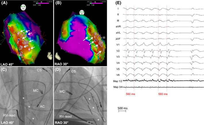
Ablation of VT1. (A, B) Electroanatomical maps. Points (I = red, II = blue, III = gray) represent corresponding pacemapping locations. Light red points and white arrows mark the ablation sights. (C, D) Corresponding angiographic images presenting the sight of ablation (antegrade transseptal approach). AC, Ablation Catheter; CS, Coronary Sinus catheter; MC, MitraClip™; RV‐Lead, Right ventricular‐lead of ICD. The white stars mark the pairs of Revivent‐TC ™ anchors. (E) Prolongation and termination of VT1 during ablation.