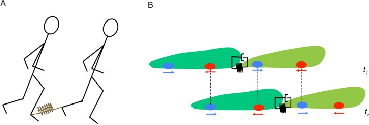
FIGURE 8:
Synchronization of a mechanically linked pair. (A) Schematic representation of two individuals moving one behind the other with their right and left ankles respectively linked through an elastic rope. The rope is shown in brown and represented by a linear spring. (B) Schematic representation of two cells following each other at two different instants of time, t1 and t2. The leading and trailing cells are shown in light and dark green, respectively. The cells are linked together via adhesion molecules modeled as a linear spring parallel to a dashpot (viscoelastic material). Ovals and arrows at the ventral surface of the cells represent TAs and the direction of the net force they exert, respectively. Dashed vertical lines show the reuse of these TAs as the pair proceeds forward.

