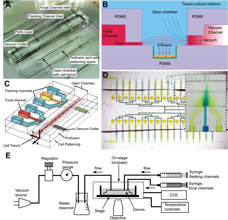
FIG. 1.
Schematics and operation of the microfluidic device. (a) Photograph of the device shows that the focal and flanking channel inlets and the vacuum outlet are introduced into the chip via a central ports layer. The focal and flanking microjets are on a middle perfusion layer, while the cell trench lies within the open chamber. (b) A cross-sectional side view (YZ plane) of the device through the channels: there is continuous flow driven by positive pressure from syringe pumps and negative pressure from vacuum channels. The molecule of interest diffuses to cells, which are patterned within trenches modified with epoxysilane/poly-lysine coating (green). (c) A 3D schematic shows two units of focal and flanking channels apposed by vacuum aspiration channels. The flanking channels squeeze the stream from the central focal channel by hydrodynamic focusing to deliver factors to cells (e.g., myotubes and myofibers) in trenches, which lie in a chamber open to the bulk cell culture medium. (d) The device consists of 32 units of focal and flanking channels, as represented by the blue and yellow dyes in the focal and flanking channels, respectively. The inset shows one unit of focal and flanking channels, showing hydrodynamic focusing. (e) Diagram of fluidic connections. For cell experiments, the device was enclosed within an on-stage incubator with temperature control and CO2 source. Panels (b) and (c) reproduced with permission from Cheng et al., in Proceedings of The 15th International Conference on Miniaturized Systems for Chemistry and Life Sciences, Seattle, 2–6 October 2011, pp. 356–358. Copyright 2011 Chemical and Biological Microsystems Society, CBMS.67

