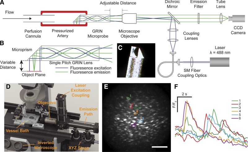
Figure 1.
Intraluminal endothelial imaging. A) Simplified schematic diagram of the endothelial microendoscopy utilizing GRIN. B) Schematic illustrating the optical excitation and emission paths through the side-viewing GRIN microprobe. The GRIN reconjugates the image plane of a conventional microscope through the length of the cylinder (green lines). The collimated input excitation light is recollimated at the output of the GRIN (blue lines). C) An image of the distal end of the GRIN microprobe with the microprism attached. The GRIN is protected inside a stainless steel sheath. D) A 3-dimensional rendering of the system on an inverted microscope showing the custom vessel bath, position of the GRIN microprobe assembly, the objective lens, XYZ translation stage for positioning the artery, and excitation coupling and emission pathway. The laser and camera are outside the image. E) Fluorescence image of the endothelium visualized using the GRIN imaging system. Scale bar, 100 μm. F) Individual baseline corrected Ca2+ signals of corresponding ROIs (E) showing spontaneous Ca2+ transients.

