
Figure 14.1.
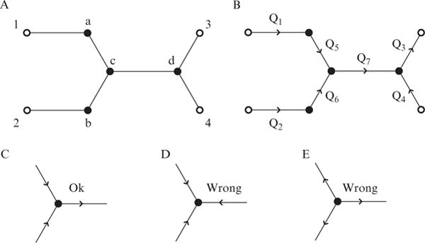
Overview of how to conceptually set up microfluidic flow problems. (A) Stick diagram of a conceptual microfluidic device. External ports with specified pressures (open circles) are labeled 1–4. Internal junctions (whose pressures will be solved for, closed circles) are labeled a–d. (B) Same diagram as in part A, except the port and junction numbers are removed for clarity. Volumetric flows to be solved for are given by Q1–7. (C–E) Overview of the correct way to set up flow directions in a microfluidic junction, while obeying the conservation of mass. Part C has the correct setup, containing both inlets and an outlet. Part D is incorrect since there are only inlets. Part E is also incorrect since there are only outlets.