
Figure 14.5.
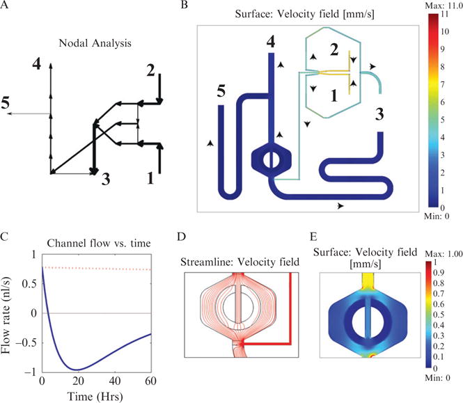
Comparison of a nodal analysis tool written in Matlab (moca) and Comsol (finite element analysis package). (A) Graph from the moca matlab script depicting flows for the device pictured in Fig. 14.4A. The arrow thickness and direction represent the volumetric flow in a channel section of the device. Numbers are the external ports of the device. (B) Flow velocity through the same chip modeled using Comsol. The magnitude of the velocity is given by the channel’s color, while the direction is indicated by the black arrows. Numbers are again the external ports. The MFD005a geometry was loaded directly from Autocad, simplifying setup. (C) Flow profile of a channel section over the course of an experiment. In previous designs, we have had problems with backflow problems over the course of an experiment, as the fluid level in the external ports is altered by flow. Modeling an experiment’s flow profile using nodal analysis helped to solve these problems, resulting in a redesign of the diversion channel’s dimensions and using larger syringes. The blue line represents fluid flow using 1-ml syringes and the red dashed line 60-ml syringes. (D) Streamline plot showing the path fluid particles take upon moving through the cell trap. While this plot was generated under running conditions, the streamlines are very similar for loading conditions (the direction of flow of course is opposite). Note that only about one fourth of the flow enters the central channel, most flow is directed around the trap. Hence, when loading, most cells will not enter the trapping region. (E) Plot of the velocity field inside the trap region. Note that the velocity is lowest inside the trap itself and considerably higher in the outer channel region. This allows nutrients to be continually replenished from the outer channel into the cell trap and helps remove cells once they outgrow the trap.