
Figure 5.
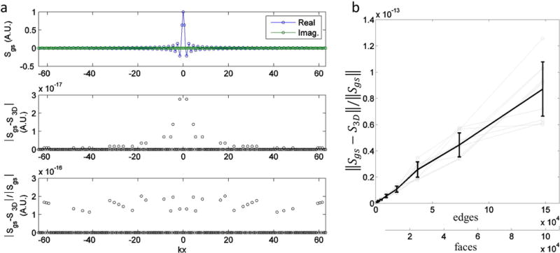
Evaluation of FT error with increasing edges in unit cube shaped triangular meshes. a) Sample-wise evaluation of the FT error. Top row) Plot of the gold standard computed using the product of sincs. Values are given in arbitrary units (A.U.) The real and imaginary components are displayed separately. Middle row) Graph of magnitude of error versus kx-axis location. Bottom row) Graph of normalized magnitude of error versus kx-axis location, excluding points where the gold standard coefficient magnitude is zero since this would result in an undefined value. b) Graph of the normalized l2-norm of the error versus the number of faces in the unit cube mesh. Gray lines indicate different shifts of the cube from the origin. The black line with error bars indicate the mean and standard deviation of the normalized error taken across all displacements.